About a month ago I bought a new to me 2006 tahoe 215 outboard with an optimax 150.
I'm starting to think that at some point the previous boat owner let a monkey under the dash. There were a couple of small issues when I lake tested the boat - as it related to gauges and things on the dash...most seemed easy to figure out, so I bought the boat. After getting into it, some seem to relate to someone goofing around behind the dash. Or what seems impossible to me, that some things left the factory and never actually worked right.
Tachometer was set to 5P instead of 6P for a optimax, leading to reading higher than reality RPM...fixed
Horn didn't work - replaced - easy...fixed
Trolling motor onboard charging system didn't work, and trolling motor won't turn.
Charger had corroded inline fuses and the fuse holder basically disintigrated into my hands when I was trying to figure out why it wouldn't charge the batteries - had to resplice in new fuse holder inline, replace fuses...fixed.
Jumper wire between trolling motor batteries to make 24v series was torn from terminal...respliced new ring terminal on jumper...fixed.
So I'm feeling pretty good about myself...and thinking...ok, most of this is wear and tear stuff..little bit of moisure, vibration, stuff breaks. Kinda weird that the tach was set to 5P...wonder if it has always been wrong (it's a 12 year old boat, it's possible no one ever really paid attention to RPM not looking correct).
Then I start looking at the voltmeter...which doesn't move. The battery has juice, the alternator charges, The boat runs great. So I start digging around behind the dash. I'm neither a mechanic or electrician.
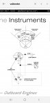
But what I'm finding makes me think this is wired wrong, If this is correct...
https://www.jamestowndistributors.com/userportal/document.do?docId=840
So if that is correct, and IF I am reading it correctly (and that's a big if), I have a problem with how I'm wired. Please read how I'm wired and confirm my understanding of what's wrong:
How I'm wired:
I have a -12V grey wire going to the blade connector for the light. That wire then continues to the Ignition terminal on the bottom half of the guage.
There is a terminal in the center of the back of the gauge according to every diagram I find that is suppose to be ground, On my wiring it's negative 12v, so that is correct. So the question is...is there a reason the I terminal and blade terminal for the light connector would have -12V wires on them? Shouldn't they be +12V?
There is a terminal across from the Ignition, which according to diagram linked above is sender (S) and not used on voltmeters...and on mine there is nothing on that terminal, just a red plastic cap. Is that really not used? Or Is this where +12V should be coming into the voltmeter?
I took this video earlier - before finding the diagram above. I *think* my problem is that the light and I terminal are suppose to be +12V, which complete the circuit with the ground in the center of the gauge. I think that's what I'm seeing in the diagram above.
However, because I am so far outside of my area of expertise I would appreciate any input. I did find a loose red blade connector behind the dash that is +12V hot and not going anywhere. (not connected to any switches or gauges). its' about a 12 gauge wire (again, I'm eyeballing this and don't do this for a living...I didn't see any labelling to how thick the wire was consider 12 gauge a guess). that could go to the blade connector on the light bulb, I would just need to add a jumper wire that goes to the I terminal. I like the idea that I'm finding the wire that originally went here...I can't find any other wires that are not already terminated some place.
Of course, if I take off this -12V grey wire I'm left with the question - where the hell did this -12V grey wire I'm pulling out of it originally go? Unless it has literally never worked from the factory (Tahoe boats have quality issues like this?) and no one ever had it fixed, it seems like this should go some place.
The only other electronics that don't work are the speakers (radio comes on but no sound) - I doubt that's related to this -12V wire
Fuel gauge gives me doubts...it's possible it's wired wrong too...haven't gotten there. So far it always reads full, but I haven't spent enough time on the boat to burn enough gas to doubt it.
Video of me showing how it's wired...
https://www.youtube.com/watch?v=8s1VVoEo1Nw
thanks for any input here.
I'm starting to think that at some point the previous boat owner let a monkey under the dash. There were a couple of small issues when I lake tested the boat - as it related to gauges and things on the dash...most seemed easy to figure out, so I bought the boat. After getting into it, some seem to relate to someone goofing around behind the dash. Or what seems impossible to me, that some things left the factory and never actually worked right.
Tachometer was set to 5P instead of 6P for a optimax, leading to reading higher than reality RPM...fixed
Horn didn't work - replaced - easy...fixed
Trolling motor onboard charging system didn't work, and trolling motor won't turn.
Charger had corroded inline fuses and the fuse holder basically disintigrated into my hands when I was trying to figure out why it wouldn't charge the batteries - had to resplice in new fuse holder inline, replace fuses...fixed.
Jumper wire between trolling motor batteries to make 24v series was torn from terminal...respliced new ring terminal on jumper...fixed.
So I'm feeling pretty good about myself...and thinking...ok, most of this is wear and tear stuff..little bit of moisure, vibration, stuff breaks. Kinda weird that the tach was set to 5P...wonder if it has always been wrong (it's a 12 year old boat, it's possible no one ever really paid attention to RPM not looking correct).
Then I start looking at the voltmeter...which doesn't move. The battery has juice, the alternator charges, The boat runs great. So I start digging around behind the dash. I'm neither a mechanic or electrician.
But what I'm finding makes me think this is wired wrong, If this is correct...
https://www.jamestowndistributors.com/userportal/document.do?docId=840
So if that is correct, and IF I am reading it correctly (and that's a big if), I have a problem with how I'm wired. Please read how I'm wired and confirm my understanding of what's wrong:
How I'm wired:
I have a -12V grey wire going to the blade connector for the light. That wire then continues to the Ignition terminal on the bottom half of the guage.
There is a terminal in the center of the back of the gauge according to every diagram I find that is suppose to be ground, On my wiring it's negative 12v, so that is correct. So the question is...is there a reason the I terminal and blade terminal for the light connector would have -12V wires on them? Shouldn't they be +12V?
There is a terminal across from the Ignition, which according to diagram linked above is sender (S) and not used on voltmeters...and on mine there is nothing on that terminal, just a red plastic cap. Is that really not used? Or Is this where +12V should be coming into the voltmeter?
I took this video earlier - before finding the diagram above. I *think* my problem is that the light and I terminal are suppose to be +12V, which complete the circuit with the ground in the center of the gauge. I think that's what I'm seeing in the diagram above.
However, because I am so far outside of my area of expertise I would appreciate any input. I did find a loose red blade connector behind the dash that is +12V hot and not going anywhere. (not connected to any switches or gauges). its' about a 12 gauge wire (again, I'm eyeballing this and don't do this for a living...I didn't see any labelling to how thick the wire was consider 12 gauge a guess). that could go to the blade connector on the light bulb, I would just need to add a jumper wire that goes to the I terminal. I like the idea that I'm finding the wire that originally went here...I can't find any other wires that are not already terminated some place.
Of course, if I take off this -12V grey wire I'm left with the question - where the hell did this -12V grey wire I'm pulling out of it originally go? Unless it has literally never worked from the factory (Tahoe boats have quality issues like this?) and no one ever had it fixed, it seems like this should go some place.
The only other electronics that don't work are the speakers (radio comes on but no sound) - I doubt that's related to this -12V wire
Fuel gauge gives me doubts...it's possible it's wired wrong too...haven't gotten there. So far it always reads full, but I haven't spent enough time on the boat to burn enough gas to doubt it.
Video of me showing how it's wired...
https://www.youtube.com/watch?v=8s1VVoEo1Nw
thanks for any input here.