Campion Re-wire project...

Swedefj40

Petty Officer 2nd Class
Joined
Jun 9, 2018
Messages
155
We bought our 1996 Campion Victoria 215 last spring, which makes us the 3rd owners of it, and with the help of you fine folks here in this forum, we were able to get the bugs out of it (alt, oil sensors, balancer, etc.) and were able to enjoy it for the rest of the summer.
39027599_10160844480165475_342557129716006912_o.jpg

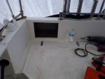
This winter I relocated the electronics to the upper shelf and got them off of the dash which obstructed my view, redid the trailer's brakes and fixed some tail lights issues.
20180811_083708.jpg

20190314_120041.jpg

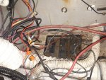
So now it's on to tackling the wiring mess that previous owners have created. Check this out...
20190306_150028.jpg

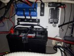
Needless to say it needs to be corrected! The plan is to replace the battery switch to a smaller "off/on/emergency combine" type and add an Argofet isolator for the charging circuit. Add a proper circuit breaker and fuse block in the engine bay and also one at the helm.

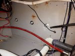
My question is this... as you can see in the last picture the battery disconnect switch is located on the transom right behind the engine. I'm thinking that if there is an electrical fire in the engine bay I'd have to reach over top of everything to get to the battery switch to power it off. Is there any reason why I can't raise the switch higher up the transom, cut a hole and install a watertight compartment into the rail above the engine cover and install the switch in that? That way I'd be able to switch batteries or shut them off without lifting the cover off. See the drawing in the picture...
20180811_152146_LI.jpg

So what do you think?
 

gm280

Supreme Mariner
Joined
Jun 26, 2011
Messages
14,590
Looks like you are in need of both a positive AND negative Buss Bar fused/circuit breaker setup. Then you can move the existing battery shut off switch and use only one leg from the battery for each polarity. Would certainly clean up the "rat's nest" seen there. Just my opinion. As for your answer, YES, anything is possible. Just make a plan and work towards it. But think it all though well before gutting it. JMHO
 

Swedefj40

Petty Officer 2nd Class
Joined
Jun 9, 2018
Messages
155
Well I finally got started on the box. I ordered some 1/2" Starboard and a Hatch and also a Blue Sea Systems Battery switch to replace the old 1,2 1+2 switch. I decided to move the location to the starboard side since it would be behind the fish cooler which would limit access to the hatch when out fishing. I also relocated the hour meter as well. I'll relocate the expansion tank so as to free up an area on the transom for my Circuit Breakers, Fuse Block and Isolator panel.
 

Attachments

  • photo322559.jpg
    photo322559.jpg
    1,013 KB · Views: 1
  • photo322560.jpg
    photo322560.jpg
    650.8 KB · Views: 1
  • photo322561.jpg
    photo322561.jpg
    1.4 MB · Views: 1

Grub54891

Vice Admiral
Joined
Jun 17, 2012
Messages
5,911
Looking good! Cleaning up that rats nest is a good idea, ABYC don't allow more that four wires on a single stud. In my opinion, if you have more than two, it's enough to warrant putting in the busses. All you need at the battery is the main cable, and the wire to the buss. The auto bilge goes to the back of the battery switch, or to the powers buss.
 

Swedefj40

Petty Officer 2nd Class
Joined
Jun 9, 2018
Messages
155
Thanks for the info. Out of curiosity, how is the hour meter supposed to be connected? The way it was originally wired it starts to run as soon as the battery switch is switched on. Shouldn't it be wire to start running only when the main engine is running? I troll a lot with the kicker. A normal fishing trip is a run of 30 to 45 minutes each way and trolling on the 15hp kicker for 6-8 hours. Doesn't make a lot of sense to be continually adding hours when the main isn't running.
 

Swedefj40

Petty Officer 2nd Class
Joined
Jun 9, 2018
Messages
155
So... I pulled the batteries out while we were in for a lengthy cold snap and charged them up and load tested them. Turns out the old "house" battery was shot! I tested the "starter" battery and it was in great shape. I also noticed that the previous owner was using a Deep Cycle battery for the starting battery instead of a proper starting battery so I'm just going to move it over to the house side and use it to replace the failed one. I then ordered an Odyssey battery for starting the engine.

Anyway, since the batteries were out, I took the time to clean up the area where the house battery was and where I'm going to mount the isolater and fuse block.

1st pic is what the battery area looked like.and the rest are self-explanatory...
 

Attachments

  • photo324767.jpg
    photo324767.jpg
    1.5 MB · Views: 0
  • photo324768.jpg
    photo324768.jpg
    1.1 MB · Views: 0
  • photo324769.jpg
    photo324769.jpg
    1.6 MB · Views: 0

sam am I

Commander
Joined
Jun 26, 2013
Messages
2,169
Looks waaaay better.........

One thing that sticks out? And it's sorta hard to tell from the angle of the photo so it might totally be a moot point BUT!! If the two batt wires in the photo below are physically (or become) pressed against the heat-sink fins edges of your Argofet isolator, if they chaf over time, temp AND vibration, they might wear through their insulation.

Might be a fuses eater, esp. if the chassis is grounded. Least of all, if they both wear through and both are shorting to the metal, this would negate the isolation of the Argofet.

Like I said, hard to tell for sure by the picture and its probably fine.

Click image for larger version  Name:	image_324769a.JPG Views:	1 Size:	326.2 KB ID:	10829557
 
Last edited:

Swedefj40

Petty Officer 2nd Class
Joined
Jun 9, 2018
Messages
155
Yeah good point, I made sure that there was enough clearance there for that very reason. I got about a quarter inch gap at the closest point and I made the bends while the heat shrink was still soft so it should keep the shape. I'll keep an eye on it though. That's #6 awg there too so it's pretty stiff at that particular spot and with those tight bends. Funny, now that I look back at that picture, I think the flash on the camera is casting a shadow behind the wire making it look a lot closer than it is. Thanks for the input!
 
Top