wiring help

winterhawk78

Seaman
Joined
Jun 20, 2017
Messages
51
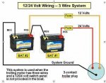
I have looked and looked for something showing me how to wire in 24v trolling motor batteries and a starting battery with quick connectors on the batteries along with disconnects, breakers and if they need to be fused or not. Something to show from the trolling batteries too the trolling motor itself. And then something from the starting battery to the fuse block and switch panel at the console. I inherited a mess from previous owner and I want to clean it up.

Thanks for the help.
 

alldodge

Moderator
Staff member
Joined
Mar 8, 2009
Messages
40,720
Could use some more info of what you have to start with. Assuming you have an OB motor. If this is the case and having a 24V trolling motor, then just need another bat for t=starting

Gen wiring Diag 2.jpg
 

Attachments

  • 12-24Vwiring 3 prong.jpg
    12-24Vwiring 3 prong.jpg
    28.7 KB · Views: 0

winterhawk78

Seaman
Joined
Jun 20, 2017
Messages
51
Here is what i am starting with. And I believe its a 71lb thrust motor guide trolling motor.

Why the need for the 3 wire system?
20180910_123403rs.jpg
 

alldodge

Moderator
Staff member
Joined
Mar 8, 2009
Messages
40,720
Why the need for the 3 wire system?

You don't need a 3 wire hook up, but many trolling motors do a 12 or 24V so this is just the one I have posted. Yours is a mess and those different size wires on the trolling bats is not great
 

winterhawk78

Seaman
Joined
Jun 20, 2017
Messages
51
You don't need a 3 wire hook up, but many trolling motors do a 12 or 24V so this is just the one I have posted. Yours is a mess and those different size wires on the trolling bats is not great

I think mine is wired with 3 wires, but I am not sure that is correct or not. It seems to run okay, haven't had any issues. But yes it is all a mess and I want to clean it up. The first diagram you posted shows fuses on the trolling cables, I believe mine has breakers. Do I need both or one or the other?
 

Silvertip

Supreme Mariner
Joined
Sep 22, 2003
Messages
28,762
Look at the control pedal for your trolling motor. If you see a switch that has 12V and 24V positions, you require either a three or four wire system. If there is no such switch, and assume you looked VERY carefully, then you need only two wires from the batteries. The next thing you need to determine is if the motor is a 12 OR 24 volt version. Google the model number to determine this or call the manufacturer. If the motor is 24 volt, the batteries need to be wired in SERIES. If its a 12 volt motor the batteries can be wired in PARALLEL. Just because there are three wires in your system does not mean all three need to be used.
 

winterhawk78

Seaman
Joined
Jun 20, 2017
Messages
51
Look at the control pedal for your trolling motor. If you see a switch that has 12V and 24V positions, you require either a three or four wire system. If there is no such switch, and assume you looked VERY carefully, then you need only two wires from the batteries. The next thing you need to determine is if the motor is a 12 OR 24 volt version. Google the model number to determine this or call the manufacturer. If the motor is 24 volt, the batteries need to be wired in SERIES. If its a 12 volt motor the batteries can be wired in PARALLEL. Just because there are three wires in your system does not mean all three need to be used.

Thanks, I will check and see what I found out.
 

winterhawk78

Seaman
Joined
Jun 20, 2017
Messages
51
Look at the control pedal for your trolling motor. If you see a switch that has 12V and 24V positions, you require either a three or four wire system. If there is no such switch, and assume you looked VERY carefully, then you need only two wires from the batteries. The next thing you need to determine is if the motor is a 12 OR 24 volt version. Google the model number to determine this or call the manufacturer. If the motor is 24 volt, the batteries need to be wired in SERIES. If its a 12 volt motor the batteries can be wired in PARALLEL. Just because there are three wires in your system does not mean all three need to be used.

I didn't see anything marked on the pedal itself, but the trolling motor clearly says its a 24v.

20180911_123329rs.jpg20180911_123419rs.jpg
 

Silvertip

Supreme Mariner
Joined
Sep 22, 2003
Messages
28,762
OK -- then you only need a two wire system with the series jumper at the batteries. If the trolling motor plug has a 12/24 volt jumper in it, then you eliminate the jumper at the batteries and run a pair of red and black wires from each battery (four wires total) to a four terminal receptacle. The jumper in the plug creates the series connection. But since you have the three wire system already, you only need to use two wires as I said. Just make sure the two in the receptacle match the two in the plug.
 

winterhawk78

Seaman
Joined
Jun 20, 2017
Messages
51
OK -- then you only need a two wire system with the series jumper at the batteries. If the trolling motor plug has a 12/24 volt jumper in it, then you eliminate the jumper at the batteries and run a pair of red and black wires from each battery (four wires total) to a four terminal receptacle. The jumper in the plug creates the series connection. But since you have the three wire system already, you only need to use two wires as I said. Just make sure the two in the receptacle match the two in the plug.

I forgot to mention that my system works now. I just want to clean it up. But I am confused as to why there is 3 wires running up front. Through all my searching I should only have 2. Could the 3rd wire just be a hot wire running to the front of the boat for powering other things?
 

winterhawk78

Seaman
Joined
Jun 20, 2017
Messages
51
Questions on trolling battery side of things...
1. What is the recommended gauge wire to run say 20ft to the front for the 24v 71lb trolling motor?
2. What kind and size breaker do I need? And where in the line does it go? Hot side? Ground side? Both?
3. And if i were to add in a battery disconnect, where in the line does that go?

Questions on the cranking battery side...
1. Shouldn't I just have a hot and ground wire running to the console area of the boat to a fuse/ grounding block?
2. What gauge wire should from to the fuse/ grounding block at console?
3. And if i were to add in a battery disconnect, where in the line does that go?
 

alldodge

Moderator
Staff member
Joined
Mar 8, 2009
Messages
40,720
Could the 3rd wire just be a hot wire running to the front of the boat for powering other things?

Its all possible, need to trace to find out why it may have been added
 

alldodge

Moderator
Staff member
Joined
Mar 8, 2009
Messages
40,720
Questions on trolling battery side of things...
1. What is the recommended gauge wire to run say 20ft to the front for the 24v 71lb trolling motor?
2. What kind and size breaker do I need? And where in the line does it go? Hot side? Ground side? Both?
3. And if i were to add in a battery disconnect, where in the line does that go?

Questions on the cranking battery side...
1. Shouldn't I just have a hot and ground wire running to the console area of the boat to a fuse/ grounding block?
2. What gauge wire should from to the fuse/ grounding block at console?
3. And if i were to add in a battery disconnect, where in the line does that go?

If you look in post 8 there is a link which advises size of wire and breaker for a given length
Breakers go on the hot side, between bat and motor
Bat disconnect, between bat and breaker, or bat and motor, either will work

If you look in post 2 it shows the layout and size wires feeding circuits
Disconnect goes between bat at your motor.
Power to console should come from other side of bat switch to fuse block buss bar
 

winterhawk78

Seaman
Joined
Jun 20, 2017
Messages
51
Its all possible, need to trace to find out why it may have been added

I will pull the trolling motor plug panel switch off the front of the boat sometime this week. Between the kids sports and rain, I have little time during the week. Maybe I can on my lunch hour tomorrow. thanks!
 

winterhawk78

Seaman
Joined
Jun 20, 2017
Messages
51
If you look in post 8 there is a link which advises size of wire and breaker for a given length
Breakers go on the hot side, between bat and motor
Bat disconnect, between bat and breaker, or bat and motor, either will work

If you look in post 2 it shows the layout and size wires feeding circuits
Disconnect goes between bat at your motor.
Power to console should come from other side of bat switch to fuse block buss bar

wasn't sure if motorguide and minn kota were the same or not
I am trying to eliminate the mess I have in post 3. I don't see why all those wires are on the battery. Shouldn't there be a main ground and hot running up front? If my thinking is correct, I would have 2 hots and 2 grounds coming off the cranking battery. The outboard hot and ground? and the hot and ground running up to the fuse block buss bar?
 

alldodge

Moderator
Staff member
Joined
Mar 8, 2009
Messages
40,720
The outboard hot and ground? and the hot and ground running up to the fuse block buss bar?

Yes that is correct, but the start cable will be larger then the one for the fuse block. Just connect the Pos cbale to the bat and go to the bat switch. On the other side of the switch go to motor and fuse panel

Compare the size breaker that is on your motor now with what is shown on the sheet. The breaker on your troll has worked for this long without issue, and could probably be used again, or as before just get the same size.

Here is Motorguide link shows 50 amp
http://www.motorguide.com/userfiles/file/Support/OwnersManuals/Standard-MotorGuide-Owners-Manual.pdf
 

winterhawk78

Seaman
Joined
Jun 20, 2017
Messages
51
Yes that is correct, but the start cable will be larger then the one for the fuse block. Just connect the Pos cbale to the bat and go to the bat switch. On the other side of the switch go to motor and fuse panel

Compare the size breaker that is on your motor now with what is shown on the sheet. The breaker on your troll has worked for this long without issue, and could probably be used again, or as before just get the same size.

Here is Motorguide link shows 50 amp
http://www.motorguide.com/userfiles/file/Support/OwnersManuals/Standard-MotorGuide-Owners-Manual.pdf

Thanks for the help. I'm sure I will have more questions.
 
Top