Wiring (Mercury) - Sanity / Idiot Check Please!

Kargh

Seaman
Joined
Aug 9, 2015
Messages
57
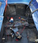
Now that I sorted most of my wiring issues, I am to the point of wiring the control box with the new harness. I've traced all the old lines with the old (spliced together) harness, created a nice diagram, shook my head a few times, and then created a new diagram. I would appreciate it if someone could take a look and tell me if it looks right or if something is out of place or should be different.

Equipment (Mercury):

Wiring Harness - Sierra 18-5511
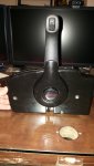
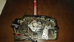
Control Box: RC881170A13

I don't know if the ignition switch in the box is the original for that box or if it was taken from something else.

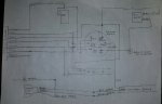
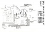
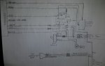
This is a diagram of the original wiring. The two grey and one black are what was spliced into the original harness. I have no idea why and some of it just doesn't make sense.
fetch


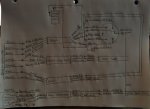
Now, based on that, this is my new diagram:
fetch


I have no idea if the 'Pink' wire is used anywhere nor any idea if the red wire from the hydraulic pump plug should be wired.
 

Attachments

  • photo249784.jpg
    photo249784.jpg
    161.1 KB · Views: 1
  • photo249785.jpg
    photo249785.jpg
    169 KB · Views: 1

mjf55

Chief Petty Officer
Joined
Jun 17, 2014
Messages
462
No Title

Kargh,
First, please keep all your wiring in this thread from now on. It is difficult to bounce between 3 threads.
Ok, now, on your planned wiring, I would not use Purple to feed the Trim / Tilt switch, use red. That way it is always available even with ignition off ( useful for the tilting (aka trailer mode).
What year engine and HP do you have. Can you post a picture of the outside of the controller?
You said you traced the wires back into the engine? Does it match this drawing?
 

Attachments

  • photo249796.jpg
    photo249796.jpg
    9.6 KB · Views: 0

Kargh

Seaman
Joined
Aug 9, 2015
Messages
57
No Title

Sure thing, I'll keep it all in this thread. Those other ones were more about the accessories and this was meant to be very specific to the harness and controls. Anyways....

Year: 1976 / 1977
Model: 1500
Serial: 4558919 / 4752690

A previous owner mashed together parts from both a '76 and '77 so I can't say with absolute confidence that all the internal motor wiring is based on 1976 or 1977 -- though they might be the same.

I did trace the wiring back to the engine but remember that the old harness was sliced into three separate sets of wires. In the drawing of the original wiring, there are three new sets of wires (two grey and one black) that are spliced into the 7 wires from the harness. I included a photo of the old wiring harness.

If you want a closeup of the ignition switch wiring itself, I can get you one. I tried to separate the wires as best as I could so they are each traceable in the image but it is still not always easy to tell.

As far as the drawing that you provided, I honestly have no idea. It shows up no bigger than 2"x1" and I can't enlarge it :D

Thanks again for your help! I'm really looking forward to getting this wiring in place. I'm hoping to finish up this part of the project today!
 

Attachments

  • photo249410.jpg
    photo249410.jpg
    92 KB · Views: 0
  • photo249811.jpg
    photo249811.jpg
    326.1 KB · Views: 0
  • photo249812.jpg
    photo249812.jpg
    378.5 KB · Views: 0

Kargh

Seaman
Joined
Aug 9, 2015
Messages
57
This should be the wiring diagram for my particular motor... except, of course, for the remote control since at some point it was swapped with a much newer version.
 

Kargh

Seaman
Joined
Aug 9, 2015
Messages
57
No Title

Well, that totally failed. Let me just add the actual image instead of a link.
 

Attachments

  • photo249817.jpg
    photo249817.jpg
    119.7 KB · Views: 2

mjf55

Chief Petty Officer
Joined
Jun 17, 2014
Messages
462
Sorry about the poor image. I thought i was posting the whole thing. Here is a link for what amounts to your wiring diagram, in living color.
http://www.maxrules.com/oldmercs/Wiring/1966ona/35.jpg

The trim/tilt addition looks ok, but as i said before, I would tie the red to red, not the purple. However, i am a little confused why only blue and green is connected at the trim pump. Are there relays there? Picture of that would be helpful.

Tach section looks ok.

Good luck.
 

Kargh

Seaman
Joined
Aug 9, 2015
Messages
57
No Title

Yeah, I have that diagram but it doesn't really do me much good as far as wiring up the ignition / control box since that isn't the control box that I have. That is to say, I don't have enough experience to mentally convert what might be on that diagram to what I see in my unit.

Here is a picture of the trim pump. I can grab a new one if there is more you'd want to see that is not shown in this image.
 

Attachments

  • photo249837.jpg
    photo249837.jpg
    102.9 KB · Views: 0

mjf55

Chief Petty Officer
Joined
Jun 17, 2014
Messages
462
Kargh. Did the boat and controller work with the spliced up wiring harness? If so, your new drawing does not match the old one, as far as harness to key switch.
For instance:
HarnessOld Key PositionNew Key Position
Yellow1 oclock - Black/Yellow stripeThru NSS to 7 oclock, yellow/red stripe
Grey3 oclock - Purple9 oclock - Yellow/Black Stripe
Black9 oclock - Yellow / Black Stripe1 oclock - Black / Yellow Strip , then to tach
WhiteThru NSS to 7oclock yellow/red stripe3 oclock - purple

So I am confused.
 

mjf55

Chief Petty Officer
Joined
Jun 17, 2014
Messages
462
I am continuing to over think this. I have attached a wiring diagram document for mercury outboards. What you need to do is verify that the engine side harness is connected as shown in the appropriate section. Then you should be able to wire the controller to match the functions.

I this does not help, then I am at the end of my knowledge and search capability. Perhaps another can jump in.

View attachment 2D - Wiring Diagrams.pdf
 

Kargh

Seaman
Joined
Aug 9, 2015
Messages
57
On the new harness drawing, I meant to put 'Orange' and not 'Pink'. Either way, the wire isn't used. I'm going to follow your table example above and create one for the old harness and new harness. I'm going to remove all the middle splicing from the equation.
Old Harness - WireToNew Harness - WireTo
YellowTop Post - NSSYellowTop Post - NSS
GreyYellow / Blk - KeyGreyYellow / Blk - Key
BlackBlack / Yellow - Key
Black / Yellow - Kill
Black - Tach
BlackBlack / Yellow - Key
Black / Yellow - Kill
Black - Tach
WhitePurple - Key
White - Tach
WhitePurple - Key
White - Tach
BrownBrown - TachBrownBrown - Tach
RedRed - KeyRedRed - Key
SalmonNot UsedOrangeNot Used

The only change I made was to move the red wire from the Tilt / Trim Switch to the red feed from the harness instead of purple from the key, per your suggestion.

I believe everything is wired the same as it was previous except that I removed all the spliced in wiring. I guess I'll find out later today when I finally have it all together.
 

Kargh

Seaman
Joined
Aug 9, 2015
Messages
57
Just wanted to report back that the wiring was a complete success. I didn't have to change a thing from the new diagram and she fired right up.

So, thanks again for idiot checking my hand drawn diagram and the suggestion on the trim/tilt switch! It all was greatly appreciated!
 

mjf55

Chief Petty Officer
Joined
Jun 17, 2014
Messages
462
Excellent. Good job. Just for clarification and for anyone else looking to do something similiar, exactly what did you do? Your new diagram in post 1 or table in post 10?
 

Kargh

Seaman
Joined
Aug 9, 2015
Messages
57
No Title

Yes to both. The table and the new diagram are the same except that in the diagram I labeled the one wire as 'Pink' instead of 'Orange'. In either case, its not used.

I've included an updated drawing that is a bit easier to follow than my original.
 

Attachments

  • photo250015.jpg
    photo250015.jpg
    235.3 KB · Views: 0
Top