Where to find replacement live well timer

nhellbaum

Cadet
Joined
May 24, 2015
Messages
18
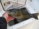
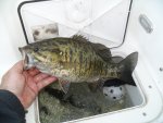
I need help finding a new live well timer for my 1989 tracker magna. It is the red "film canister" looking item. Mine has 3 wires exiting out the back that leads to a harness plug to the switch. It has CAPLUGS RCL-16 on the unit. I would really like to find a replacement that just plugs into the existing 3 wire connector.

Anyone know where to find one??
 

gm280

Supreme Mariner
Joined
Jun 26, 2011
Messages
14,592
nhellbaum, I don't know about the exact replacement for your live well timer, but they do offer those timers everywhere. The three wires are power (battery or from a switched power source) ground and output to the pump. The other wire from the pump will also go to ground. So you could use the connector off the old one and slice it into a new one for a plug and play setup.

If you are inventive, you can even make your own if you have some electronic background. I have posted such builds on here before. JMHO!
 

nhellbaum

Cadet
Joined
May 24, 2015
Messages
18
gm280,
I have found 4 wire units that look very similar. My current timer unit is completely connected to the aerator switch (all three wires from the timer plug into the switch) the wire to the actual pump runs from the switch. I assume the three wires are for power, ground, and timer signal. My aerator switch has manual,off,auto settings.

If I were to get the 4 wire timer, can i just connect the power, ground, and timer signal wires back to the switch and leave the 4th wire unconnected? What would the 4th wire be for?
 

gm280

Supreme Mariner
Joined
Jun 26, 2011
Messages
14,592
gm280,
I have found 4 wire units that look very similar. My current timer unit is completely connected to the aerator switch (all three wires from the timer plug into the switch) the wire to the actual pump runs from the switch. I assume the three wires are for power, ground, and timer signal. My aerator switch has manual,off,auto settings.

If I were to get the 4 wire timer, can i just connect the power, ground, and timer signal wires back to the switch and leave the 4th wire unconnected? What would the 4th wire be for?

Okay, not being there and seeing this for myself, I can only assume a four wire timer would have a ground going to the pump as well. Post some pictures of your present switch/timer setup and wiring with the switch and I may can explain it better. JMHO!
 

gm280

Supreme Mariner
Joined
Jun 26, 2011
Messages
14,592
Okay a little more info. I researched and there are loads of three wire replacement timers available all over the place. And I did see some four wire setups, but the forth wire is a yellow loop wire that comes out and feed right back into the timer. Not having a schematic for that yellow wire loop, I can only assume it is for some type external variable resistor or potentiometer to allow the operator to change the on/off times intervals. But that is merely a guess. The basic wiring is Red for positive input. Green for positive wire output that goes to the pump. Black for the ground both for the input and possibly the pump as well and if a forth wire, Yellow loop wire.
 

nhellbaum

Cadet
Joined
May 24, 2015
Messages
18
Ok thanks! I know the 3 wire timers you're talking about. I was avoiding those since they look completely different and dont have the connector plug that currently exists on mine. I imagine they would work fine to hook up to the original switch. I think on a lot of those 4 wire timers, the 4th wire is a different timer setting that can be connected. Green wire might be on for 1 minute, off for 3 and the yellow might be on for 1, off for 5. I assume that output wire is what is connected back to the "AUTO" side of my switch and it sends the signal to the pump from there.
 

sam am I

Commander
Joined
Jun 26, 2013
Messages
2,169
When you first turn on the pump, about how long is the run time time verses the off time? I assume the "on" verses "off" is non-adjustable?

BTW, that isn't a/the timer part number per-se, its just a generic cap (from a specific cap manu) that the timer manu's used to pot the timer in.......

https://www.caplugs.com/series/Long-...Caps/1201.html
 
Last edited:

N8cas

Cadet
Joined
Mar 27, 2016
Messages
6
I will be doing the same exact repair as the Original poster this weekend. I will report back how it goes. I do not know how to adjust the time ( I don't know if the timer is even adjustable).
 

sam am I

Commander
Joined
Jun 26, 2013
Messages
2,169
Okay, thx....please do. I was curious about what those 3 wire timing intervals were fix at. I believe they were set to run the pump at something like 10 sec on each 30 sec.......If it's broke and you had never ran it before, it may remain a mystery......

Are you then replacing it with a 4 or 5 wire type?
 

N8cas

Cadet
Joined
Mar 27, 2016
Messages
6
4 wire. Here's the replacement (see below?). I have one of my really old timer modules that work. I can't figure out the timing intervals for it (yet). As long as it goes off and on when I'm done and I don't kill my fish - it's all good.
 

N8cas

Cadet
Joined
Mar 27, 2016
Messages
6


I have to get the small one to work in place of the old bigger one. That old one connects with a pin connector,too. Do I use the old wires and connect them into the newer smaller timer module pin connector at the capsule? Or, should I cut the old pin connector off and splice it to the red green and black bare wires on the newer one?
 

sam am I

Commander
Joined
Jun 26, 2013
Messages
2,169
Either or............RS has the pins tho (might have to buy a old size housing to get the 3 [get 4 pins, you'll mess at least one up] pins you'll need) , they're just standard molex pins. If you have a smaller mandrel crimper, could just unpin and re-use the old housing (de-pinning tool below or use fine tipped needle noses) and go back into the emptied old housing with the newly crimped on pins of your new smaller capsule's wires. Would be a tiddier way then splicing..but, on the other hand, splicing and heat shrinking soldered wires would be fine too.

6 of one, 1/2 dozen of another eh? Both would work fine.

Hmmm.......Too bad there just isn't a OEM'ish plug-n-pray replacement type available, this seems a bit sort of a PITA. I'll do some digging while you do some soldering/crimping :)

02740224_01_a04c177d-dd97-4b72-ab2a-19434fb148ac.jpeg 02740223_00_4e6edd7e-36c4-44f2-9190-52a4ff440c66.jpeg bct-13.jpg

http://www.aeroelectric.com/articles/matenlok/matenlok.html


Or, if you want a new 3 position connector/housing to go along with new pins.........

https://www.digikey.com/product-sear...20M-N-L%20NATL

https://www.digikey.com/product-deta...2CT-ND/1794811


Use your native adobe reader to view 3D pdf
 

Attachments

  • ENG_CVM_1-480726-0_C.pdf
    248 KB · Views: 1
Last edited:

sam am I

Commander
Joined
Jun 26, 2013
Messages
2,169
edit ^^^^

Not "old size" but odd size :facepalm:
 
Last edited:

N8cas

Cadet
Joined
Mar 27, 2016
Messages
6
This is great! Thanks very much for your help. I start the work tomorrow and will let you know how it goes. I MIGHT have a question or two as I'm not electrically inclined. Thanks again!
 

sam am I

Commander
Joined
Jun 26, 2013
Messages
2,169
yvw, and np, fire away. And me either, I just play inclined here on iBoats! I have a Doc act going on over on eyeDoc's!......J/K ;)
 
Last edited:

N8cas

Cadet
Joined
Mar 27, 2016
Messages
6
The replacement worked ! I connected the old pin connector and wires to the new with waterproof twist connectors


It's not pretty, but it'll get the job done until it doesn't. Thanks for your help!!

Btw, the timer for the new module (from eBay) is 1 minute on - 3 minutes off.
 

sam am I

Commander
Joined
Jun 26, 2013
Messages
2,169
Looks good enough to be considered another gov't job well done to me!! And thx for the info.

So on for 1 minute per 4 total minutes.......25% duty cycle.
 

sam am I

Commander
Joined
Jun 26, 2013
Messages
2,169

Attachments

  • photo241746.jpg
    photo241746.jpg
    265.1 KB · Views: 0
  • photo241747.jpg
    photo241747.jpg
    193 KB · Views: 0
  • photo241748.jpg
    photo241748.jpg
    297.6 KB · Views: 0
  • photo241749.jpg
    photo241749.jpg
    284.3 KB · Views: 0
Last edited by a moderator:
Top