replacing glass fuse terminal block, need help

Status
Not open for further replies.

fishinjunky

Cadet
Joined
Dec 9, 2015
Messages
12
I have very little electric understanding . work good w picture ... I have 1992 bass tracker replacing fuse panel and Need to know how to set up wiring . please help. 1. Old fuse panel. 2. New fuse panel
 

Attachments

  • 20151202_133429_HDR-1.jpg
    20151202_133429_HDR-1.jpg
    203.7 KB · Views: 5
  • 20151205_184254_HDR-1.jpg
    20151205_184254_HDR-1.jpg
    98.6 KB · Views: 7

NYBo

Admiral
Joined
Oct 23, 2008
Messages
7,107
On the new panel, the negative feed from the battery connects to the stud on the strip on the far right. This should be an 8 or 10 gauge wire that goes directly to the negative battery terminal. The negative side of the your accessory circuits connect to the screws on that strip.

The positive battery feed from the main breaker or fuse (should be about a foot from the battery) connects to the stud on the strip to the right of the fuses. This should also be 8 or 10 gauge. The positive side of your accessory circuits connect to the screws to the left of the individual fuses. If you need an unfused positive feed, connect it to on of the screws immediately to the right of the fuses (on the same strip as the main positive connection)

Use ring terminals for all of these connections, and connect only one wire at each connection point.
 
Last edited:

alldodge

Moderator
Staff member
Joined
Mar 8, 2009
Messages
40,746
Just to give you a pic to look at You don't have to attach stuff like I have shown, just an example. All negative returns from lights, radio and other stuff get attached at the Negative buss bar fuse.jpg
 
Last edited:

NYBo

Admiral
Joined
Oct 23, 2008
Messages
7,107
Nice diagram, AD. But the arrow for the main positive connection should be pointing at the stud sticking up from the strip.
 

batman99

Petty Officer 1st Class
Joined
Sep 13, 2012
Messages
393
Agree. 1 x stud for "+" wire and 1 x stud for "-" wire. And remember to install large 30 Amp inline fuse near battery's "+" post as well.

For a good picture, surf http://www.12voltplanet.co.uk/fuses-guide-uses.html and scroll down 1 x page. Very clean logical diagram - that might help as well. Note: Most boats don't have frame ground (like a vehicle or trailer). Thus, parallel "+" and "-" wires to downstream load items.

Hope this helps as well...
 
Last edited:

NYBo

Admiral
Joined
Oct 23, 2008
Messages
7,107
Most boats don't have frame ground (like a vehicle or trailer). Thus, parallel "+" and "-" wires to downstream load items.
Even if it did, like an aluminum boat, NEVER use the hull as a ground conductor!
 

gm280

Supreme Mariner
Joined
Jun 26, 2011
Messages
14,592
One thing I would like to add. The fuse panel does not have to be within one foot of the battery. Usually such a fuse panel is located at the helm or underneath the helm for central access. BUT, you do have to have a fusible or circuit breaker connection at the battery for the positive wire that feeds the fuse panel. That way if there is a short along any of the wires, the fuse blows at the battery and everything is safe. JMHO!
 

alldodge

Moderator
Staff member
Joined
Mar 8, 2009
Messages
40,746
You guys are getting nit-picky, must be getting old like me ;) . I was pointing at the buss bar not where to connect the wire, just trying to clarify. Guess I should find a place to post so I can get comments before posting final posting, oh well not going to happen.

All Ya'll have fun and play nice
 

fishinjunky

Cadet
Joined
Dec 9, 2015
Messages
12
Ok one one issue. Not sure if I have this wired right. Cant get livewell pump to work. The orange wire on right is positive side and it goes to battery meter . it come on.the green with blue wire goes to boat lights but wire is hot and will not go to positive side
 

NYBo

Admiral
Joined
Oct 23, 2008
Messages
7,107
Ok one one issue. Not sure if I have this wired right. Cant get livewell pump to work. The orange wire on right is positive side and it goes to battery meter . it come on.the green with blue wire goes to boat lights but wire is hot and will not go to positive side

Sorry, but I can't follow this. Did you intend to post a picture?

The negative wire from the pump goes to the negative bus. The positive wire from the pump goes to the switch. The wire from the other side of the switch goes to one of the fuse terminals on the far left. If you have a timer instead of a plain switch, follow the directions or labels to ensure you hook up the positive side the correct way. The battery meter and boat lights have nothing to do with the livewell pump.
 

alldodge

Moderator
Staff member
Joined
Mar 8, 2009
Messages
40,746
My first thought when I see this is Rats Nest
fetch


Looks like you have a lot of yellow wire. Looking at a bunch of wires but not knowing where they go is meaningless.
Look at it this way
Below is a similar setup but look at it with this in mond. Red wires are hot and Black are negative.
Gen Wiring Diagram.jpg
 

NYBo

Admiral
Joined
Oct 23, 2008
Messages
7,107
Yellow is also approved for use as DC negative, so don['t use it for any positive connections.
 

fishrdan

Admiral
Joined
Jan 25, 2008
Messages
6,989
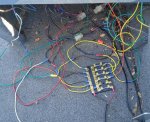
There isn't any easy way to say it, so I'm just going to go for it.... That's a mess of wiring waiting to cause problems! Take this with a grain of salt and I'm trying to help get it cleaned up and working.

- I see black wires, butt connected to yellow wires that have a ring terminal on them, and then the yellow wire connected to the negative buss bar, wouldn't it have been easier to just put a ring terminal on the black wire?
- Using all one color of wire (yellow) is an accident waiting to happen, or at least use yellow for positive and black for negative, not + and - both yellow.
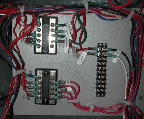
- Try to put a ring terminal directly on any wire if possible, cut out the butt connected jumper wires.
- I don't see a heavy 8 to 10ga wire feeding back to the battery, only small 14-16ga wires. If you pull a good load across that fuse panel it would/could melt your feed wire going back to the battery, while leaving all the fuses on the panel still functional. ***FIRE***
- flip your + input wire to the fuse panel 180* so it's not laying across the negative buss bar.

I would (and have done):
1- mount the fuse panel were it's going.
2- crimp ring terminals onto each wire with enough slack to reach the fuse panel, but not 2-5 feet of extra wire, maybe a couple extra inches in case you need to re-crimp.
3- fuse main 8-10ga + feed wire at battery and then connect batt wires to fuse panel
4- only black wires to the negative buss bar, then other colored wires to indicate the accessory on the positive side

Yeah, it's going to be a pain attaching all the wires to the fuse panel as you will most likely be laying down and reaching up to connect everything, but the finished product will be much better.

Hope this helps and good luck with your project!
 

gm280

Supreme Mariner
Joined
Jun 26, 2011
Messages
14,592
I personally would have to redo that entire wiring effort. The first thing you need to do, is plan out how the wires will come into the fuse panel and go out from it. In other words, if you want your bilge pump on the first terminal, then cut those wire long enough to fit that fuse terminals with just a little bit extra. Like fishrdan said, not 2 feet extras, but a mere couple inches. And try to route them in such a way that once all of them are cut crimped and wired, you can zip tie them in nice channeled bundles to keep the rats nest looking nice. And then you will have a very nice and properly wired fuse panel. It just takes time and proper wiring techniques.

MainCB-WiringBehind.jpg


Here is kind of what I am talking about. You can see how the wires are channeled together and not run all over the place. And this person even took the time to label each wire for future use.

images


This is more how I like to wire things. Neat, orderly, and so ease to find any issue if the need arises.

It just takes a little time and effort to accomplish this. You don't have to have any special electronic abilities other then wanting to wire things properly. :thumb:
 

fishinjunky

Cadet
Joined
Dec 9, 2015
Messages
12
Ok still having little trouble. I have a wire that connects to speedometer and voltmeter which is has current in it. Hooked to the ground the 2 has power like motor was running. The nav. Lights has a blue and Gray wires. I have gray ground and power when on neg also has power .
I do get power on int. Lights the bilge pump and aerator man. Only.... The main positive and negative wire are correct...
 

alldodge

Moderator
Staff member
Joined
Mar 8, 2009
Messages
40,746
Your really making this hard for us to help, We Need Pics

I have a wire that connects to speedometer and voltmeter which is has current in it.
The wire should only have power to it when the ignition is ON

Hooked to the ground the 2 has power like motor was running.

Which two have power on them, the Nav and speedo?

The nav. Lights has a blue and Gray wires. I have gray ground and power when on neg also has power .

Blue could be lights, but gray should be your tachometer, but you have power on everything, at least it sounds like

I do get power on int. Lights the bilge pump and aerator man. Only.... The main positive and negative wire are correct...

I don't understand other then your main battery terminals are on correctly

NEED PICS
 
Status
Not open for further replies.
Top