1988 Imperial V220 low budget

JaCrispy

Petty Officer 1st Class
Joined
Jul 8, 2014
Messages
391
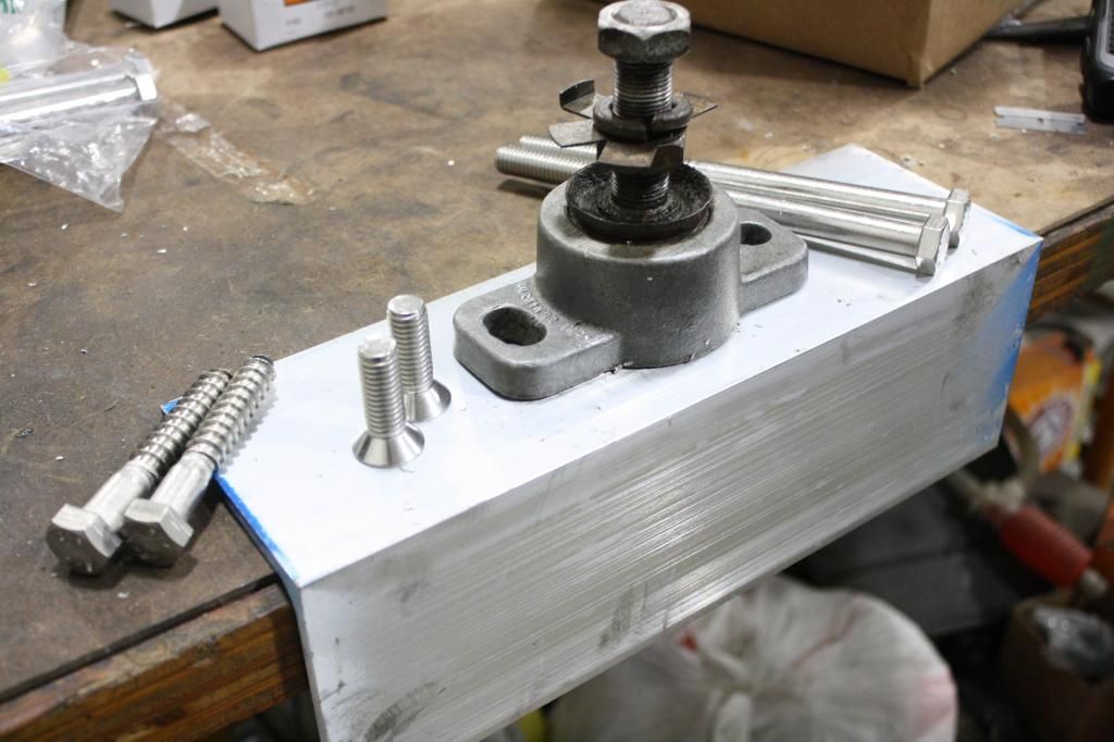
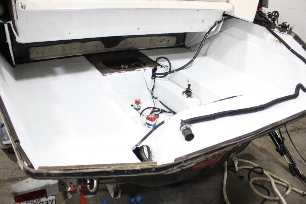
Thanks for the replies. Part of the reason for not doing them right now is there's a second smaller width stringer about 1 1/2" inches outside of the engine mounts that support the "deck" in the engine compartment. Digging out the engine mounts would surely open up Pandoras Box. I can't go there this time around and feel the current stringers can support my modifications. So here's the idea, 4x4" aluminum angle with 1/2" lag bolts vertical into the stringer, 1/2" botls through the stringer and angle, 1/2" countersink bolts mounting the engine mount to the aluminum. Might 5200 the angle down too.

IMG_6842.jpg
 

tpenfield

Moderator
Staff member
Joined
Jul 18, 2011
Messages
17,705
What is interesting ( to me ) is that I believe Imperial went out of business in 1989, just 1 year past when your boat was made. It is surprising that they had invested in new tooling (presumably) to go to the new 2 (or 3) piece design at that stage. Many boat companies continued with the tabbed-in floor/deck into the 1990's.

My brother owned a 1988 24 foot Imperial, cruiser model. . . . bought it new.

No real way to tell if your engine mounting mod will hold since we cannot see it first hand . . . that is an assessment that you will have to make.
 

JaCrispy

Petty Officer 1st Class
Joined
Jul 8, 2014
Messages
391
I skimmed through your build, you had some access with the removable hatch in your deck. I do not have that. The only opening in the deck is a small, roughly 15-18" square storage. So to really do it right, I need to remove the whole cap and inner liner/cockpit section. I actually would like to proceed with that at some point being it's the only way to get to the fuel tank as well. You can see from this image the cockpit section contains the back bench seat and runs all the way up to the bulkhead at the cuddy entry. I need to make a gantry to remove that and the cap for sure, it's like a boat within a boat.

IMG_6837.jpg
 

tpenfield

Moderator
Staff member
Joined
Jul 18, 2011
Messages
17,705
Yup, looks like it was only meant to go together, not come apart. I have a feeling we will see more boats of similar constraints with restoration needs over the next few years as the newer construction design boats become of "that age".
 

tpenfield

Moderator
Staff member
Joined
Jul 18, 2011
Messages
17,705
An additional thought, seeing the picture, you could do a rebuild of only the engine mount stringers and possibly the bulkhead up against the fuel tank. That is provided the two main stringers that run along the fuel tank are OK.

It would be a good time to take a few core samples and see if the moisture is isolated or wide spread. If it were just in your engine mount stringers, I'd fix them now and be done with the repairs. If it is wide spread to the bulkhead and main stringers, then not an easy thing nor an easy decision as you stated.
 

alldodge

Moderator
Staff member
Joined
Mar 8, 2009
Messages
40,743
A little bad news now.... So I found my stringers a little soft when I removed the lag bolts. I actually had a couple pull up a while back. I know what I "should do" to repair it, but I decided it just wasn't in the game plan this time around so I'm making up some new mounts through bolting some aluminum angle. I'll throw up some pics when the materials come in next week.

Part of why I'm not removing the stringers is the design of my boat. I guess they call it a 3 piece hull (hull, cap and a separate deck area). So to get to the stringers I'd have to remove the cap, then remove the inner piece. I just don't have the time or funds for that right now. The transom is solid so the new mounts should work fine.

I don't see your new mounts doing the job for long. If you don't dig them out there could be a lot more issues later. You don't have to put it back exactly like you found it. Mentioned and from the pic that there is little room on the side. What about digging the whole stringer out and putting it back without the gap (if it's easier)?
 

JaCrispy

Petty Officer 1st Class
Joined
Jul 8, 2014
Messages
391
I don't see your new mounts doing the job for long. If you don't dig them out there could be a lot more issues later. You don't have to put it back exactly like you found it. Mentioned and from the pic that there is little room on the side. What about digging the whole stringer out and putting it back without the gap (if it's easier)?

I think some of you guys like seeing people grind out fiberglass. lol

Good idea, so is the pour in method which I considered, but I'm going to take my chances with the new modifications. I'll keep that idea in mind though, I was wondering how it's going to be a pain in the butt working in that tight space later on when I cut them out.
 

jc55

Senior Chief Petty Officer
Joined
Nov 3, 2006
Messages
665
I think some of you guys like seeing people grind out fiberglass. lol

Who, us? Here on this site?:grouphug: Never!

I would think that you could take her out a couple times then take the drive off and recheck your coupler alignment with the mercruiser alignment tool (which will tell you if your front mounts are moving).
 

Woodonglass

Supreme Mariner
Joined
Dec 29, 2009
Messages
25,924
I'm fairly confident you can get your Motor Mounts in good enough shape to attach the motor securely. But as I alluded to in post #39 if your stringers are compromised to a severe extent, and depending on how good the factory did at glassing them to the hull and how much glass they used, then the structural integrity of the hull is at risk. A 22ft hull going over big wakes and waves undergoes an extreme amount of stress. I certainly would hate to hear of a hull failure. But it is your boat and your risk. I wish you well. Just make sure to have you PFD's on board and at the ready at all times!!!;)
 
Last edited:

JaCrispy

Petty Officer 1st Class
Joined
Jul 8, 2014
Messages
391
Getting ready to do some assembly and have a couple questions on the gimbal bearing.

1) The new bearing has an offset inner race, one side is flush, the other the inner race protrudes about 1/4". Is this an issue?

2) Is the grease appropriate for the gimbal bearing?

3) I have a new transom seal, what sealant should I use for various transom components? I like to put a thin layer of silicone usually on parts like the trim sender seal, water tube seal, etc. Not a gobbing amount, just a thin layer for insurance.

New gimbal bearing

IMG_6845.jpg


IMG_6843.jpg


grease
IMG_6846.jpg
 

alldodge

Moderator
Staff member
Joined
Mar 8, 2009
Messages
40,743
Getting ready to do some assembly and have a couple questions on the gimbal bearing.

1) The new bearing has an offset inner race, one side is flush, the other the inner race protrudes about 1/4". Is this an issue?
Prior to 1984 the two cutouts on the face were installed outward, after 1984 the cuts were installed inward. Install the bearing with the extension facing toward the front of the boat
2) Is the grease appropriate for the gimbal bearing?
As Bondo says, "any grease is better then no grease" The grease you have should be fine. Does your gimbal bearing have a hole in the side or is it a sealed bearing. If sealed you can't grease it
3) I have a new transom seal, what sealant should I use for various transom components? I like to put a thin layer of silicone usually on parts like the trim sender seal, water tube seal, etc. Not a gobbing amount, just a thin layer for insurance.
Don't use silicone on the transom seal, leave it dry. Some have used a bit of 3M adhesive on the O-ring to assembly housing to keep it in place while installing. Cannot find anything in the manuals indicating using any kind of sealant. You could use some anti-seize on the screws which hold the trim senders. Silicone doesn't last long when exposed to water for long term. Silicone is also a lubricate when wet and can cause gaskets and such to slide before it dries.
 

JaCrispy

Petty Officer 1st Class
Joined
Jul 8, 2014
Messages
391
Thanks. All is good. I called the place I got the bearing from and they said it was redesigned and to install as you said. Grease hole is lined up. Also installed the transom seal dry. The new seals are not shaped so I used paperclips to hold it in place while assembling. Once there was slight pressure, just so the gasket didn't fall out, I just pulled the clips out.
 

tpenfield

Moderator
Staff member
Joined
Jul 18, 2011
Messages
17,705
Another one of the million uses for a paper clip. :thumb:

Seeing the transom assembly reminds me of something . . .

The exhaust 'duct' on the Mercruiser transom assemblies have always bothered me . . . it seems way too small for the exhaust to make it through there in any efficient manner. I mean it starts out in a 3 or 4" tube for each side of the engine, and then merges at the base of the "y" pipe, only to be stuffed through the small transom opening and on into the outdrive.

I'm sure Mercruiser has done the science and the math . . . Maybe it is no worse than an automotive application, but it just looks too restrictive, especially for the big blocks.
 

JaCrispy

Petty Officer 1st Class
Joined
Jul 8, 2014
Messages
391
Yeah, I don't know if it helps or hurts the exhaust design. When it exits the riser the ID is only like 2.5". But yeah, then opens up and hits a bottle neck. I wanted to put a set of switched through-hull exhaust but that ain't happening this time.

I had another parts "kit" FAIL. All the crap I ordered nothing came with the shift shaft seal. Actually, one kit did come with one but it was 5/8" od and mine are 3/4". So another delay.

Meanwhile, anyone know what this is? (not the pen lol) Came with the shift cable kit.

IMG_6853.jpg
 

alldodge

Moderator
Staff member
Joined
Mar 8, 2009
Messages
40,743
Yeah, I don't know if it helps or hurts the exhaust design. When it exits the riser the ID is only like 2.5". But yeah, then opens up and hits a bottle neck. I wanted to put a set of switched through-hull exhaust but that ain't happening this time.

I had another parts "kit" FAIL. All the crap I ordered nothing came with the shift shaft seal. Actually, one kit did come with one but it was 5/8" od and mine are 3/4". So another delay.

Meanwhile, anyone know what this is? (not the pen lol) Came with the shift cable kit.

IMG_6853.jpg

I think that is the shift cable seal (item 30), trying to find a pick which shows it being installed.
http://www.mercruiserparts.com/Show...3&bnbr=20&bdesc=TRANSOM+PLATE+AND+SHIFT+CABLE

18759.png
 

JaCrispy

Petty Officer 1st Class
Joined
Jul 8, 2014
Messages
391
Thanks. I can't find that piece anywhere on my old cable and don't recall it anywhere else. Maybe for a different model?

I'm doing some preliminary engine fitting and can't get the engine aligned. The engine is too high, as if the fiber washers are too thick. Looks to be a hair over 1/16" off. I tried raising/lowering the engine, rotating the crank, etc. No change.
 

alldodge

Moderator
Staff member
Joined
Mar 8, 2009
Messages
40,743
You have the fiber washer and then the spring washer are inside the fiber washer, and nothing else all the rest is on top right?

You did install a new gimbal bearing and they can be stiff. Can the alignment tool move the bearing center?
 

JaCrispy

Petty Officer 1st Class
Joined
Jul 8, 2014
Messages
391
Yes, the fiber washer and spring washer are installed properly, as you said. I put the alignment tool in the bearing and tapped all around with a mallet but the bearing feels pretty solid. I try a BFH.
 
Top