Restoring 1986 Sea Nymph SS155 (pics)

Piece715

Senior Chief Petty Officer
Joined
Jan 26, 2009
Messages
757
Re: Restoring 1986 Sea Nymph SS155 (pics)

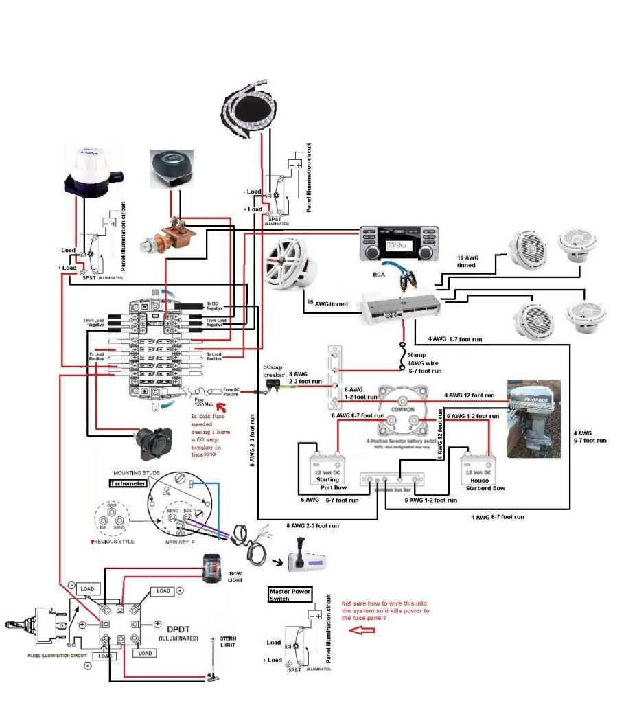
Ok im in the process of buying wire. Going with 2 six gallon tanks the splashwell is filled. The 12 gallon tank would not fit in the splashwell. This situation has forced me to move the batteries to the bow seating one in front of each console. The question is what gauge wiring will work for this set up? I know people don't recommend this set up but i have no other choice and it will distribute weight well. The run im guess would be around 12 feet and that is prob an over estimation. I am not sure how many amps the starter draws either. The motor is a 50hp Evinrude model E50 BELCO. Now the set up includes a blue seas fuse block and a battery switch.

This is the run down of the wiring as im seeing it; Just need confirmation or ideas for better set up. The runs will be from battery to battery switch (2-3 foot run), from battery switch to fuse block (1-2 foot run), the direct run for the battery to motor is about 12 feet.

The cranking battery will be run in parallel to the deep cycle. The batteries will then be wired to the switch like so StandardBatterySwitchWiring.jpg.
All loads will be wired to the COM which will be the engine and the fuse block. Does the negative in the picture going from engine to bat 1 also do this in my set up and then a neg wire run from neg bat post to fuse block?? guess confused how to incorporate the fuse block and switch. The positive will go from COM on isolator switch to positive on fuse block with a master power toggle switch in line like so InstrumentPanelWiring.jpg. How would stereo work into this? Would i want to run it through the fuse block or just wire directly to batteries as the system requires inline fuses from batt to amp.

OK i think im confusing myself. SOMEONE please help :facepalm:

I know this was a large post. If ya need clarification on my thoughts please ask. Im needing recommendations, suggestions, diagrams, etc. I have saved all the stickies in the electrical section and know what gauge wire I need for everything except the long run of battery wire. Guess the other main question is a general run down of wiring all the components: dual batteries, an isolator switch, fuse block, and amplified sound system. Thus concludes my jumbled novel! thank u will be here all night :D!

EDIT: Just had a moment of clarity. Im guessing the audio system would be wired to the COM port for positive with the ground running to the fuse block? The positive will still have an inline 50 amp fuse as recommended for the amp. This sound correct?
 

Piece715

Senior Chief Petty Officer
Joined
Jan 26, 2009
Messages
757
Re: Restoring 1986 Sea Nymph SS155 (pics)

Ok just got back from looking at the boat. It looks like the 12 feet is pretty much the run of the engine to batteries. Also the two batteries will need a 6-7 foot run between them to run in parallel.. This possible? I understand the + end of the wiring now that i have looked at the wiring diagrams for the two pieces but still confused on the ground set up and the wiring of the amp into this set up.

Here are the pics of the installation instructions on the fuse block and isolator switch:
(for some reason iboats isnt letting me post any pics right now so as soon as that is fixed ill post em)
 

Piece715

Senior Chief Petty Officer
Joined
Jan 26, 2009
Messages
757
Re: Restoring 1986 Sea Nymph SS155 (pics)

Weird! Looks like i falsely accused iboats.... My other computer that I was using last night and this morning won't allow me to post any pics it just errors; even in photobucket. Oh well here are those two pics finally

photo(2).JPG

The switch according to installation instructions recommends 4/0 AWG per terminal. Will this be enough despite the long runs?

photo.JPG
 

Piece715

Senior Chief Petty Officer
Joined
Jan 26, 2009
Messages
757
Re: Restoring 1986 Sea Nymph SS155 (pics)

I posted the wiring questions in the electrical forum... getting some thing ironed out before I start. I am going to try to make a wiring diagram today and post it here and there for final critiquing... Wish me luck!
 

Piece715

Senior Chief Petty Officer
Joined
Jan 26, 2009
Messages
757
Re: Restoring 1986 Sea Nymph SS155 (pics)

Ok well here is my first attempt at a wiring schematic for the boat. I have this posted in the electronic forum as well. I am posting it here in case one of the experts stumbles across it. I know there are errors; please help me out its the last phase of the boat before i get it on the water. I will post the pic, an attachment if you need to blow it up and then the link to the other thread:
http://forums.iboats.com/showthread.php?t=539613

Sea_Nymph_wiring_diagram.jpg


Sea_Nymph_wiring_diagram.jpg
 

sqbtr

Senior Chief Petty Officer
Joined
Feb 23, 2010
Messages
716
Re: Restoring 1986 Sea Nymph SS155 (pics)

Your nav light wiring has me totally confused. You are showing the ground from the light returning to the switch and eight posts on the switch.


The power should feed both middle terminals, in one positition, lets say up, the bottom terms would be receiving power one wire to bow one to stern. in the down positition you would want only stern lt on by running jumper from bottom term to top term.

I went one further and gave the switch two feeds, one from the selected batt, one hot at all times from house batt. With the master sw off only the anchor will light even with the switch in nav.
 

Piece715

Senior Chief Petty Officer
Joined
Jan 26, 2009
Messages
757
Re: Restoring 1986 Sea Nymph SS155 (pics)

Your nav light wiring has me totally confused. You are showing the ground from the light returning to the switch and eight posts on the switch.

Ya the swithces have me confused... The issue I'm running into is that the tips of this switches are illuminated. The diagram of the switch was pulled from the company. This DPDT switch does have 8 terminals the middles ones on top and bottom are the circuit for the illumination of the tip (it glows white when powered and when the load is turn on the tip turns red). Its the illumination circuit that is throwing me. I am going to look at the packaging today and the switches and see if i can get a handle more on this.

What your explaining is this switch correct? But this doesn't have the illumination circuit... does it get wired just the same and the illumination circuit is internal? So the grounds of the loads dont go to switch they go straight to the fuse block?
Thanks for looking sqbtr this is definitely a learning process for me :facepalm:

untitled.jpg
 

Piece715

Senior Chief Petty Officer
Joined
Jan 26, 2009
Messages
757
Re: Restoring 1986 Sea Nymph SS155 (pics)

Here I slapped this together based off a basic 6 terminal switch. Nav lights.JPG

If this is correct... can some explain why the original diagram has "load -" next to each terminal accepting a positive feed?
 

GT1000000

Rear Admiral
Joined
Jul 13, 2011
Messages
4,916
Re: Restoring 1986 Sea Nymph SS155 (pics)

Here I slapped this together based off a basic 6 terminal switch. View attachment 139549

If this is correct... can some explain why the original diagram has "load -" next to each terminal accepting a positive feed?

It is basically indicating that every load ends in a ground to complete the circuit...kind of depends on the electrical engineer/wizard that drew the original schematic...

Hope that makes sense...

BTW, you are doing an amazing job on your Sea Nymph...I have been lurking for quite some time, just hadn't finished reading through your thread...

I was just looking through your wiring diagram and only noticed two things I would try and change...If possible...
1- Switch the House Battery and the Start Battery positions, so the start batt has a shorter run to the motor...
2- What looks like a connector for your trolling Motor receptacle, I would have it wired directly to the main power bus coming from the batts and add a 50 or 60 amp circuit breaker between the bus and the receptacle...it looks like you are using the ATO type fuses in the panel, and those can't really handle the load demands of a trolling motor...you would need to upgrade to a Maxi-fuse...

The fuse you are asking about between the breaker and the panel is sort of redundant, but if the circuit breaker should fail, it could prevent a major meltdown...while I don't really think it is absolutely necessary, if it is already there, you could leave it as a back-up...question, what is the amp rating on it at what voltage? And the same location is a good place to put the Master on/off switch, just make sure it is rated to handle all of the fused power requirements plus about 10 percent...

Hope some of this helps...

Keep up the great work...

GT1M
 

Piece715

Senior Chief Petty Officer
Joined
Jan 26, 2009
Messages
757
Re: Restoring 1986 Sea Nymph SS155 (pics)

Thanks so much for the response GT. It comforting to know that im sort of on the right track. The receptacle you are referring to is actually a 12v accessory plug; sorry should have made that more clear. The lay of the schematic is all over the place and is not representative of the layout of the boat. So tonight's project is to take the tips that i have received and make it a layout of the vessel and edit the schematic. Thanks again for your help... im sure i will need much more. And thank you for ur kind words about my work very up lifting for the end of a long day! :D Be looking for a revised copy of the diagram soon :facepalm:
 

sqbtr

Senior Chief Petty Officer
Joined
Feb 23, 2010
Messages
716
Re: Restoring 1986 Sea Nymph SS155 (pics)

The ammended diiagram is closer, but, you are still missing the ground for the switch illumination.

Can you post the make and model of the switch?
 

Piece715

Senior Chief Petty Officer
Joined
Jan 26, 2009
Messages
757
Re: Restoring 1986 Sea Nymph SS155 (pics)

The switches that I have purchased are Sierra TG40300 SPST ON-OFF and Sierra TG19520 DPDT ON-OFF-ON. They have an illuminated tip that when powered on they illuminate white and then illuminate red when the load is switched on. Is it possible to wire the switches like the tach to where the lights won't glow until the nav lights are turn on? Here are the diagrams that I found for each switch

400xSIE-TG195201.jpg 400xSIE-TG403001.jpg

@GT: Not sure if you were asking about the fuse block or just the fuse. It states that "suitable main circuit protection of not more than 125A rating should be provided ahead of this device with an interrupt current rating consistent with the battery capacity."

Here is the technical stuff:
Blue Sea Systems ST Blade Fuse Block (PN5026)
Voltage Maximum Operating32V DC
Amperage Maximum Operating (per circuit)30 Amps
Amperage Maximum Operating (per block)100 Amps
Fuse TypeATO? or ATC? fuses
Screw Terminal#8-32 Screws with captive star lock washer
Mounting#8 Screw (M4)

[h=2]Blow Delay Curve[/h]
ATO_ATC_Fuse.jpg
 

sqbtr

Senior Chief Petty Officer
Joined
Feb 23, 2010
Messages
716
Re: Restoring 1986 Sea Nymph SS155 (pics)

Acording to the diagram the upper middle term gets it feed from the illumination circuit, jump from nav light power I would also tie any other instrument lighting to that circuit
The lower middle term goes to ground.
 

Piece715

Senior Chief Petty Officer
Joined
Jan 26, 2009
Messages
757
Re: Restoring 1986 Sea Nymph SS155 (pics)

Ok I think i may have it... key word think... just trying have it straight before i begin. Thank you for ur time sqbtr! If i wire it like this3 pos switch.JPG and then wire all the illumination circuits to the nav lighting ON position power then the other switches illumination won't happen until the nav lights are flipped on?; like how the back light for the tach will be wired. Hope that makes sense.
 

sqbtr

Senior Chief Petty Officer
Joined
Feb 23, 2010
Messages
716
Re: Restoring 1986 Sea Nymph SS155 (pics)

Thats it.
 

Piece715

Senior Chief Petty Officer
Joined
Jan 26, 2009
Messages
757
Re: Restoring 1986 Sea Nymph SS155 (pics)

Thats it.

Thank you so much for your help!
So putting a picture to the power to the illuminating white tip not turning on until the nav lights are switched on would go like so? or will i need a jumper still from accessory load to illumination power terminal. Because in my head this rough drawing set up is saying the tips wont light until the power for the nav lights is switched on
400xSIE-TG403001.jpg

EDIT: Just looking at it.... Can i just daisy chain ( i think that is the correct term) all the grounds so i dont have so many wires going into the fuse block? like so
switches daisy chain neg.JPG
 

Todd4

Petty Officer 2nd Class
Joined
Feb 11, 2012
Messages
111
Re: Restoring 1986 Sea Nymph SS155 (pics)

No that won't work.

Wired that way your switch will only glow red when powering your BOW light. It'll never glow white and it won't glow red when powering only your STERN light. Here's a write up I've worked on in WORD that might help explain it. I may be late to the party. Hope it doesn't confuse you MORE.:eek:


The full wiring diagram of your DPDT is wrong. The lights will never light.

Your 6 pole diagram is “OK” but the NAV and ANCHOR label on the SWITCH are reversed (conventionally, when the switch lever is up it powers the lower terminals – when the switch lever is down it powers the upper terminals). Just drives me nuts looking at it - other than that it CAN work the way it is. But.... I really like sqbtr’s idea of powering the switch from two feeds but a diagram would help to fully understand it – definitely worth exploring.

Explaining how the lights work in the switch will be fun, without confusing you more. First, totally ignore powering the NAV and STERN – you can use your 6 pole diagram later. Think of the two switch terminals top middle (12:00 o’clock) and bottom middle (6:00 o’clock) as an independent circuit within the switch itself - all those two terminals do is power the lights IN the switch – nothing more (no NAV, no STERN). So, first permanently ground the 6:00 o’clock terminal just as you would any other black ground wire on your boat (for example: on your fuse block, next to your cigarette lighter ground). Then, temporarily connect 12V power to the 12:00 o’clock terminal (directly to any positive battery post, for this demonstration). The switch will glow red when the lever is up; the switch will glow red when the lever is down; the switch will glow white when the lever is in the middle. (Yes, the switch is NOT turning anything on or off – keep ignoring that for a while). As long as power is going to the 12:00 o’clock terminal the switch will glow a color – ALWAYS. See the problem? No way to turn off the lights in the switch when wired like this. I’m obviously not recommending to hook the switch up this way – I’m simply explaining it’s operation.

As a slightly more complicated analogy: let’s hook your switch up to your car. IF you wired the 12:00 o’clock terminal to the headlights in your car (and grounded the 6:00 o’clock terminal) so the 12:00 o’clock terminal only saw power while the headlights were on - the switch would glow only when the headlights were on, and not when the headlights were off. Therefore, the switch would glow only in the dark when your headlights were on, but would NOT glow during the day when your headlights were off; and, more importantly, the switch would not glow while the car was parked with the headlights off – thus not draining the battery. This would be an acceptable way to light your switch in a car.

So, you need to decide how you want to power the lights IN your switch. If you want the switch constantly glowing whenever a battery is hooked up (day and night, engine running or not) – wire the 12:00 o’clock terminal on the switch to any positive on your fuse block. Then use your battery selector to turn the switch lights off for storage. How will you be powering the backlighting for the tach? Is it on all the time? Or only when the engine is actually running? Or do you have a separate backlight button for the tack (probably not)? You might be able to tie the switch light (12:00 o’clock terminal) into the tach’s backlighting circuit. Once you decide how you want to wire the lights in the switch then wire your NAV and STERN lights the way you have them wired in your 6 pole diagram above.

I still like sqbtr’s idea of wiring the STERN light off the “selected battery” or the house battery while anchored (night fishing) but I can’t figure that out without using a diode (sqbtr?). But, here is a way to wire the BOW NAV to the selected battery and the STERN NAV to the house battery and the STERN ANCHOR to the house battery (no BOW ANCHOR) . (I also ‘flipped’ it so your switch nameplate would be correct - sorry.)

SWITCH TERMINAL WIRE
CLOCK POSITION DESCRIPTION
[EDIT: corrected, but not used - updated in posts below]
12:00 – from 12V+ power for switch lights
1:30 - to 12V+ to STERN light (ANCHOR and NAV)
3:00 – from 12V+ from house battery
4:30 – Jumper to 1:30 terminal position
6:00 – from 12V- for switch light (ground)
7:30 – to 12V+ BOW light (NAV only)
9:00 – from 12V+ from selected battery (12V+ from fuse block)
10:30 – leave blank

OK - where did I make a mistake? LOL

Todd
 

Todd4

Petty Officer 2nd Class
Joined
Feb 11, 2012
Messages
111
Re: Restoring 1986 Sea Nymph SS155 (pics)

Quick look at Post 356 DPDT switch:

I think nothing powers your white light and nothing powers your red light when in STERN ANCHOR mode. Red light will glow only when in BOW/NAV mode. I'll look over closer later.

Todd
 

Piece715

Senior Chief Petty Officer
Joined
Jan 26, 2009
Messages
757
Re: Restoring 1986 Sea Nymph SS155 (pics)

Ok sounds good... I think i posted that as u were typing up ur explanation... so that is pre ur explanation. I did a quick once through of ur explanation and it makes sense so far. Thank you for taking the time! The ideal set up that I am looking for is to have no illumination until the nav lights are switched on like the headlight explanation. Basically I want to wire it to where the nav lights control all back lighting i.e. tach and other switches. In summary: During day no glow except red when switch is activated; Switches illuminate white when nav lights are turned on and then turn red when activated. But is there a way to break down the white/red light action like that? Im thinking not. I would be happy with just illumination when nav lights are powered and no lights at all during the day if needed; no biggie
 

Todd4

Petty Officer 2nd Class
Joined
Feb 11, 2012
Messages
111
Re: Restoring 1986 Sea Nymph SS155 (pics)

OK - I'm at work so it may take me a long time to post a reply after I start typing it (consequently, I don't see any updates after I start typing) - and, apparently I cannot edit my posts like I thought I was doing. My Post #357 ("It won't work") was refering to your Post #354 wiring diagram. Sorry for any confusion I may have caused. Your "ideal set up" description in post #359 is what I would go for, too. I'll look over your latest diagram in Post #356 and comment later (work permitting:D). I've had to figure out a lot of wiring (switches, relays, etc) on motorcycles in the past. Once you understand what you have, what you want, and get it down on paper - the rest is easy! LOL

Todd
 
Top