Stringer Design Question

76SeaRay

Lieutenant Junior Grade
Joined
Aug 24, 2017
Messages
1,047
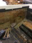
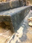
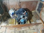
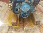
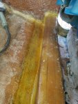
This is what I found when I opened up the floor to replace the transom. I cut the floor back about 8 inches away from the transom and cutout the floor and stringers. Here are the port and starboard cross sections of the floor and stringers. In the picture labeled stringers port A, I annotated it with where the question exists. That is, should the floor be left essentially floating where the arrow points? Would it be better when I replace the stringers to support that point from the hull. As you can also see there is only a little bit of plywood that supports the engine mounts, at least it seems that way looking at the cross section.
Stringers Port A.jpgStringers Starboard A.jpg
 

GA_Boater

Honorary Moderator Emeritus
Joined
May 24, 2011
Messages
49,038
FYI - The pics are showing up, 79.

Sorry, no advice to offer about the stringers/motor mounts.
 

froggy1150

Master Chief Petty Officer
Joined
Nov 3, 2017
Messages
802
Omc stringer???? Looks nothing like mine. I had what added up to 6x10x44 inch blocks where motor mounts were......
 

tpenfield

Moderator
Staff member
Joined
Jul 18, 2011
Messages
17,698
You could build it better than is was. Make the inboard stringer go to the hull.
 

Woodonglass

Supreme Mariner
Joined
Dec 29, 2009
Messages
25,924
Soo are you just replacing stringers, Motor Mounts, and transom from the cut point? From what I see in the pics, I believe the foam is 2# foam. And I believe that's all that would be needed on the go back. Stringer design as shown seems fine. It looks like the Floating portion is for the Non Load Bearing Motor Well and bilge. You have two outer and one center load bearing stringer which should be fine. Pics of the entire inside of the boat would also help
 

76SeaRay

Lieutenant Junior Grade
Joined
Aug 24, 2017
Messages
1,047
Forward from Transom.jpg
 

Attachments

  • Engine Bay.jpg
    Engine Bay.jpg
    517.4 KB · Views: 15
  • Engine Mount Shelf.jpg
    Engine Mount Shelf.jpg
    451.1 KB · Views: 15

76SeaRay

Lieutenant Junior Grade
Joined
Aug 24, 2017
Messages
1,047
Here is a pic from the port stern with only partial deconstruct when I was first starting. Fuel tank is still in it but I had pulled the plywood off the top of it. Including a couple of pics of the boat from outside just before I moved it from Colorado to Washington. In good enough shape to restore.

Floor Partial Deconstruct.jpg
 

Attachments

  • Boat 1.jpg
    Boat 1.jpg
    275.4 KB · Views: 11
  • Boat 2.jpg
    Boat 2.jpg
    314.3 KB · Views: 11

Scott Danforth

Grumpy Vintage Moderator still playing with boats
Staff member
Joined
Jul 23, 2011
Messages
47,496
stand on the stern and get a whole shot of the floor/stringers.

most of that will need to come out anyway
 

Mad Props

Lieutenant Commander
Joined
Jul 8, 2016
Messages
1,766
Yep, that stringer design is totally fine.. Its only in the motor mount area and it transfers the load to the fwd bulkhead and the transom.

Ive noticed in my boat and many others I've seen on here, most stringers tend to fall over a strake which is naturally going to be stiffer because of the curvature of the glass. Thinking maybe thats why they kept that part floating to keep it away from the hull in a weaker area.

My bigger concern with that design is the wood is so thin that your motor mount lag bolts would most likely protrude the whole way thru into the foam cavity allowing water to get under the deck.
 

froggy1150

Master Chief Petty Officer
Joined
Nov 3, 2017
Messages
802
This is how my stringer was. It has 4 motor mounts. 2 in the rear and 2 in the front. I put it back the way it came out. When I finish this part I am going to tie more of it to the transom in prep for when I do switch drives. I have a "plan idea" for this. It will be making a "transom Insert" that drops in with the correct keyhole completed. I would then glue that insert in and put kickers that tie into the original motor stringers. Then tab it all real good. I have not drawn it up yet but as I build this out I will plan for this option. I am using the current drive right now cuz motor is a solid Ford 302 with a freshly rebuilt drive.
 

Attachments

  • photo304176.jpg
    photo304176.jpg
    1.2 MB · Views: 11
  • photo306094.jpg
    photo306094.jpg
    1.6 MB · Views: 11
  • photo306095.jpg
    photo306095.jpg
    1.8 MB · Views: 11

76SeaRay

Lieutenant Junior Grade
Joined
Aug 24, 2017
Messages
1,047
Thanks, I was thinking about doing something similar with the floating portion, that is, box it in completely, bed it with PB to the hull bottom and increase the thickness of the "shelf" to get better engagement of lag bolts for the motor mounts (they did go all the way through before). I am shooting a little in the dark on fit in that I don't have a replacement engine yet. It had a 76 vintage 351 Windsor but I am putting in a 5.7L Vortec. I am thinking the 5.7L mounts can be adjusted for similar fit to the 351W and that I don't need to increase or decrease the height of the mounting "shelf" but instead reinforce it with the added support. Maybe I box it in from the transom to the front of the engine bay and the leave that middle stringer floating forward of the engine bay.
 

froggy1150

Master Chief Petty Officer
Joined
Nov 3, 2017
Messages
802
My motor mounts are solid wood laminated together 2x6 2x8 2x10.
that's what came out. My motor mount lag bolts are all either 4" or 5" long. They are completely In wood. Looking at your pic your original lag bolts were only in contact with 1" of wood? Wow. I would have been scared that they would pull out in bad water. Not positive but your new setup hangs from transom with 2 mounts to help stabilize. Where those mounts land I would make it beefy.
 

76SeaRay

Lieutenant Junior Grade
Joined
Aug 24, 2017
Messages
1,047
So, yes it has been a long time getting back to the stringers and floor but underway with that now since I am semi-retired. Anyway, here is what I exposed after taking the floor off around the engine bay and digging out the foam. So far I haven't found any real connection to the hull bottom except at the sides of the floor and where the inner stringer hits the hull (see pictures above in thread). The outside stringer seems to be completely floating and the cross rib is floating about an inch above the bottom. The cross rib runs all the way across but the center was rotted out. I am thinking that I need to bed the outer stringer, bed the rib, and extend the floating engine mount shelf down and bed it.

Starboard Side Engine Bay Stringers.jpg


Starboard Side Engine Bay Rib.jpg

Port Side Engine Bay Rib.jpg
 

76SeaRay

Lieutenant Junior Grade
Joined
Aug 24, 2017
Messages
1,047
So, I have almost a 1 inch gap and it appears that the factory just relied upon the foam to flow under the stringers and ribs as I haven't found any bedding material. I plan to bring the floating corner down so I end up with three supporting stringers in the area of the engine bay. I have a couple of questions based on this drawing. How should the stringer material (I will be using 3/4 inch marine plywood) meet the hull, picture number 1 or picture number 2? Is the 1/2 inch gap for bedding correct? How often do you bed the stringers and how long should the bedding material extend as in picture 3?

Thanks
Stringer Bedding.gif
 

todhunter

Canoeist
Joined
Sep 15, 2020
Messages
1,241
I did #1 and just filled the gap along the entire length of the stringer with PB. You could do #2 and use less PB, but it's more work, and you likely wont get the hull contour 100% right on the stringer anyhow. But that's ok...that's what PB is good for.

There is zero spacing in my bedding. I used 3 small blocks of foam about 1/4" thick along the entire span of the stringer (12ft long) to give a small gap to pipe PB into. Going with method #1 above, you will have a nice size gap on the inside of the stringer to pipe PB into, so you don't need to lift them up high at all.
 

76SeaRay

Lieutenant Junior Grade
Joined
Aug 24, 2017
Messages
1,047
So, 1/4 inch gap is more normal than the 1/2 inch gap and fill it all the way along instead of spaced spot PB. Will do... Thanks...
 

todhunter

Canoeist
Joined
Sep 15, 2020
Messages
1,241
Right. I don't think there's anything inherently wrong with a 1/2" gap...you'll just use a lot more PB. And you'll be surprised how much resin you'll go through bedding in stringers and bulkheads...I know I was.
 
Top