Stringer repair

bjf66

Chief Petty Officer
Joined
Dec 6, 2016
Messages
406
No Title

aluminium wedge back from machinest not bad to have 2 day turn around, picked up saturday
trimmed up centres, however left the wedge rough so I could get a good bond with epoxy
cut out the outside, wedge came up okay

for now will fit the Arneson drive with 304 S/S bolts until I figure what to do about the 17-4 PH studs

Need to located the wedge plate in correct location on transom, and 1/2" holes for studs, and then look at cutting out 4" hole to get the nose of drive fro m outside of transom

took a few picture of wedge plate on the arneson drive
 

Attachments

  • photo264399.JPG
    photo264399.JPG
    126.1 KB · Views: 2
  • photo264400.JPG
    photo264400.JPG
    131.8 KB · Views: 2
  • photo264401.JPG
    photo264401.JPG
    81.9 KB · Views: 2
  • photo264402.JPG
    photo264402.JPG
    75.4 KB · Views: 2
  • photo264403.JPG
    photo264403.JPG
    83.3 KB · Views: 2

bjf66

Chief Petty Officer
Joined
Dec 6, 2016
Messages
406
had the day of work on monday so start measuring up the transom as needed to drill 1/2" holes for mounting the surface drive, and cutting 100mm Dia hole out for nose of surface drive to come throu
Plenty of measuring was nervous about cutting the hole
holes had to be drilled perpendicular to 12 degree transom, managed to mock up the alum wedge to achieve the desired 12 degrees angle for surface drive

cut out the 85mm hole in transom with hole saw,, used router, and chisel
Im glad that over
The core cample looked okay, there was small section which looked like a cavity 5mm deep, which was on the inner glass work of transom when I added the PB to smooth up transom
However the laminated structure of 3*18mm marine ply looked perfect...happy man
Set up the wedge plate again on transom, and will epoxy it on this week, then can start to laminate the alum wedge into transom and start smoothing up the transom
If all goes well could be trial fitting the surface drive next week
 

Attachments

  • IMG_6923 top view of hole.JPG
    IMG_6923 top view of hole.JPG
    267.3 KB · Views: 1
  • IMG 6923.jpeg
    IMG 6923.jpeg
    58.2 KB · Views: 1
  • IMG_6924.JPG
    IMG_6924.JPG
    81.9 KB · Views: 1
  • IMG_6926.JPG
    IMG_6926.JPG
    105.3 KB · Views: 1

bjf66

Chief Petty Officer
Joined
Dec 6, 2016
Messages
406
had the day of work on monday so start measuring up the transom as needed to drill 1/2" holes for mounting the surface drive, and cutting 100mm Dia hole out for nose of surface drive to come through
Plenty of measuring was nervous about cutting the hole
holes had to be drilled perpendicular to 12 degree transom, managed to mock up the alum wedge to achieve the desired 12 degrees angle for surface drive

cut out the hole in 85mm thick transom with hole saw,, used router, and chisel
I'm glad that's over, it took some time to get through and nearly stuffed the drill in process
The core sample looked excellent, there was small section which looked like a cavity 5mm deep, which was on the inner glass work of transom when I added the PB to smooth up transom, and not in the lamination
However the laminated structure of 3*18mm marine ply looked perfect...happy man
Set up the wedge plate again on transom, and will epoxy it on this week, then can start to laminate the alum wedge into transom and start smoothing up the transom
If all goes well could be trial fitting the surface drive next week
 

bjf66

Chief Petty Officer
Joined
Dec 6, 2016
Messages
406
please refer to photos
 

Attachments

  • IMG_6922.JPG
    IMG_6922.JPG
    78.7 KB · Views: 1
  • IMG_6923 top view of hole.JPG
    IMG_6923 top view of hole.JPG
    267.3 KB · Views: 1
  • IMG_6926.JPG
    IMG_6926.JPG
    105.3 KB · Views: 1
  • IMG_6925.JPG
    IMG_6925.JPG
    88.3 KB · Views: 1

bjf66

Chief Petty Officer
Joined
Dec 6, 2016
Messages
406
No Title

Had trial fitting of the surface drive today, had it in/out 3 times as had to make some extra clearance on inside hole
Managed to get the hole alignment correct, and decided to drill out the 1/2" holes to 16mm to allow for 316 stainless tube 16mm OD /12.8mm ID to sleeve between bolt and transom
Its was a tight fit getting the 1/2" S/S studs back into holes....used a little lube

Once I have the surface drive mounting correct and all epoxied in, we will have to make backing plates, and drill holes fro the trim ram and steering ram

Trial fit went well
centre of shaft on surface drive is close to 4" above floor, tried the universals, and pulled out the Hallcraft Z-Drive which will give us another 4" height to get to the gearbox
The Z-drive centre plate needs to have the width reduced to 20"
Go a little confidence boost this afternoon seeing the surface drive hanging off the back
 

Attachments

  • photo264825.JPG
    photo264825.JPG
    103.5 KB · Views: 1
  • photo264826.JPG
    photo264826.JPG
    89 KB · Views: 1
  • photo264827.JPG
    photo264827.JPG
    78.9 KB · Views: 0
  • photo264828.JPG
    photo264828.JPG
    89.4 KB · Views: 1

bjf66

Chief Petty Officer
Joined
Dec 6, 2016
Messages
406
No Title

started to position the parallel drive to see how it worked out for length form transom, found I could save 80mm in length by not using the 1350 universals
There seems to be plenty of room under the parallel drive mid plate, I possibly may have enough height coming off the transom to not install the parallel drive which was going to be utilised to step up the to the engine centre line
This would certainly push engine back to transom a further 200mm, however would then lose the function of being able to change the gearing of the surface drive to tune the boat and prop

Will have to bolt sump, and crash gearbox to engine and drop in boat and see how it all looks

The problem this boat was never originally designed for surface drive, and was a custom build so have no criteria where engine is supposed to be

a few pictures attached
 

Attachments

  • photo265152.JPG
    photo265152.JPG
    92.5 KB · Views: 1
  • photo265153.JPG
    photo265153.JPG
    92.6 KB · Views: 1
  • photo265154.JPG
    photo265154.JPG
    98.1 KB · Views: 1
  • photo265155.JPG
    photo265155.JPG
    101 KB · Views: 1

bjf66

Chief Petty Officer
Joined
Dec 6, 2016
Messages
406
No Title

trial fitting of engine, sump and Daytona cash gearbox just to see whether the engine plate I had fitted, and how gearbox tail shaft lined up with Z-drive flange
engine is on slight angle (haven't measured this yet), however sump is sitting on floor with 1/2" ply sandwiched between, just to ensure I had adequate clearance

I could drop the front engine plate another inch as back of gearbox needs to come up slightly to be inline with Z-drive
Unfortunately will need to make a new rear mid plate

need to figure out what universal I will use between Z-drive and gearbox need to ensure this is shortest possible length
Then need to see whether the engine is going to be in correct place to have the boat balanced
I haven't though about fuel tanks yet, as may need to put this down the rear of boat above the Z-drive to add some weight to counter engine being so far forward

If this doesn't work will have to spin motor around, and flip the Z-drive shaft over to the other side of drive and turn this into parallel drive, and move parallel forward and engine backwards
If this case need to have a long driveshaft, flanged or splined to connect parallel drive and arneson surface drive

Will run 2* 70x100mmx6mm aluminium angles for engine rails at top of stringer and bolt the engine, plates and Z drive off this

anyway time to think about this stuff now, before we its too late and all fibre glassing done
anyways few more pics
 

Attachments

  • IMG_6944.JPG
    IMG_6944.JPG
    97 KB · Views: 0
  • IMG_6945.JPG
    IMG_6945.JPG
    116.3 KB · Views: 0
  • IMG_6946.JPG
    IMG_6946.JPG
    101 KB · Views: 0
  • photo265486.JPG
    photo265486.JPG
    126.6 KB · Views: 0
  • photo265487.JPG
    photo265487.JPG
    107.2 KB · Views: 0
  • IMG_6949.JPG
    IMG_6949.JPG
    99.4 KB · Views: 0
  • IMG_6957.JPG
    IMG_6957.JPG
    67.5 KB · Views: 0

bjf66

Chief Petty Officer
Joined
Dec 6, 2016
Messages
406
No Title

Made up new templates for the engine front and mid plates to get the engine lower between the stringers
Will make these from 6mm aluminium plates
made shopping list for the Dana Spicer universals, Companion flanges, and yokes. decided we would use 1410 universals instead of 1350.
Cheaper to import directly from USA as tried several shops over here and no one has any stock, and price is 3X would you can import for
used 1.5" Dia hole saw to cut some weep holes from outer stringer into floor
Normally the drain hole would be in lower centre of transom, however the surface drive is there, so im thinking not to have a drain hole, and just use large bilge pump
managed to come across some older picture of similar levi design hull
Looking to take the surface drive off and epoxy the aluminium wedge to the transom, then can start tidy the transom up
 

Attachments

  • photo266660.jpg
    photo266660.jpg
    23 KB · Views: 0
  • photo266661.jpg
    photo266661.jpg
    63.8 KB · Views: 0

bjf66

Chief Petty Officer
Joined
Dec 6, 2016
Messages
406
No Title

took off surface drive tonight, and had a look at the cavity which was in transom after cutting the 100mm hole out for the surface drive
This was air gap between the original fibreglass and the new laminated transom. Must of been a little thin on the PB glue with bolting up new transom
Decided to grind the cavity out with rotary file to be sure, and them used West 105/206/403 fibres to fill cavity
I used the epoxy to wet out the inner hole to seal the exposed surface of wood, as I will be using the same epoxy to glue the aluminium wedge plate on to transom
 

Attachments

  • photo264629.JPG
    photo264629.JPG
    81.9 KB · Views: 0
  • photo266799.JPG
    photo266799.JPG
    105.1 KB · Views: 0
  • photo266800.JPG
    photo266800.JPG
    91.1 KB · Views: 0

bjf66

Chief Petty Officer
Joined
Dec 6, 2016
Messages
406
Been a little slow in posting some updates this month, as been waiting for parts to arrive for universal joints

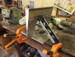
Ended up epoxying the aluminium wedge using west system (105/206 /406 filler), I was a little concerned whether the bond would be okay with the aluminium plate
However grooved back of the plate out, drilled numerous holes in it, and as recommended by local boat building company to apply the resin unfilled to both surfaces first as primer, and then use 40 grit sandpaper to roughen the back of aluminium plate up to reduce risk of the aluminium oxidised layer, then mixed in the 406 filler
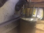
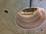
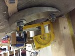
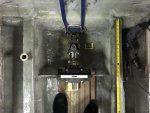
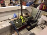
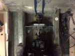
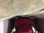
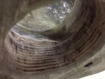
Placed a paint can wrapped in newspaper inside the hole, so when bolted up the epoxy is being squeezed outward and through the drilled holes when bolts were tightened, not too tight left a joint of 3mm
worked like a charm
Had to apply some heat as only had the 206 hardener here, and with 6-8 C temperature needed a little encouragement to set.
Cleaned this up, applied heater for 8 hours, managed to get the back of transom up to 18-22 C
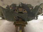
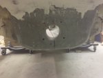
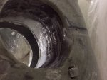
Then encapsulated the aluminium wedge plate in Vinyl Ester, layering 2oz CSM, 17oz Multi-woven fabric, 2oz CSM, 27oz multi-woven fabric.
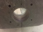
Cleaned up hole, blended inner alum plate and hole, applied coating of VE /filler to seal any exposed timber

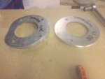
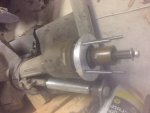
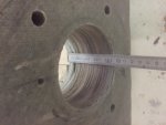
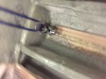
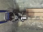
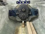
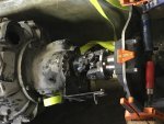
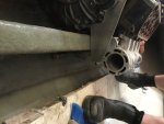
Decided to use Dana Spicer 1410 universals, so was checking over the parts that arrived and found that one of the companion flanges for the Z-drive had incorrect bore, should of been 1.19" (30.4mm) ID and ended up arriving at 1.09" (27.6mm ID), so will need to use reamer to take out to correct size
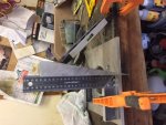
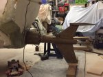
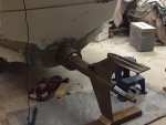
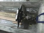
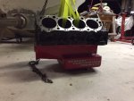
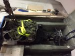
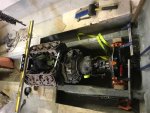
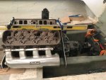
Made up new engine plates out of 6mm alum plate, I am thinking may need to change the front plate to 10mm
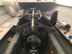
Looking to make up some rails to attach to inner stringer to support engine plates, Z-drive mid plate, and see whether we can add some bracing to tie the engine into into the stringers

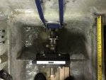
The front engine plate is 1400mm (55") from the rear transom, the total boat length is 6300 (248"), which is 22% of length, a few people have informed me < 25% should be okay
MY CONCERN IS WHERE TO PUT THE FUEL TANKS, as concerned about the balance and weight moving forward
- use tank in between stringers, I actual have one 2000mm long x 500mm W x 220mm H which would fit
- use twin tanks at back

any views on the fuel tank location are welcome
IMG_7353.JPG IMG_7354.JPG IMG_7451.JPG IMG_7455.JPG IMG_7456.JPG IMG_7457.JPG
 

Baylinerchuck

Commander
Joined
Jul 29, 2016
Messages
2,726
I have no input on where to put fuel tanks. I am really enjoying your build. Looks like a lot of fun. Keep the posts coming. 👍🏼
 

Scott Danforth

Grumpy Vintage Moderator still playing with boats
Staff member
Joined
Jul 23, 2011
Messages
47,482
your going to have to get the boat on the water running on a portable tank, then start moving weight forward and aft to figure out where to put the fuel tanks.
 

bjf66

Chief Petty Officer
Joined
Dec 6, 2016
Messages
406
I was afraid you were going to tell me that
I'm hoping it doesn't turn into submarine when I throw it in the drink
 

bjf66

Chief Petty Officer
Joined
Dec 6, 2016
Messages
406
Its been a why since i posted guess got bogged down with work and travelling
have the surface drive back on transom placed the 1410 universal and yokes in and set up looks aligned
set engine plates up, need to be trimmed, and then started looking at the exhaust

I have a few BBC here so haven't decided which one to use yet, however was going to try the smaller 402 or 454 ci twin turbo setup in which case the small water cooled logs should work

So tried to fit the water cooled logs, found the back of the log was hitting floor

lifted the front of engine 15mm, now engine on 3 degree angle, however clearance issues at back, very close to stringer perhaps 6mm clearance
when I finish glassing floor the water cool log will most probably hit floor

so now in 2 minds what to do
1. run the turbo dry up turned exhaust I have in picture
2. fabricate some others which would most probably be dry although I do have a set of wet off shore headers
3. or bite the bullet and trim 25mm off the top of the stringer, recap the stringer with glass, and taper the floor from outside stringer to insider stringer

The two inner stringers are 275x70mm so most probably not going to miss 25mm in height from the front of engine back

I checkout the floor and found out its Gurit H80 (80kg/m3 core foam) sold by Allinex (Nuplex), however thinking of vening the cuts up so just in front of engine and then taking out to the outer stringers, and then put in new rear section on either side.
Need approx. 1500x550mm wide either side
Then if centre stringers were cut down 25mm then could slope the floor down into the gunnels
This would give plenty of clearance around the exhaust whether used water cooled or dry, and would suit the standard deck height 9.8" BBC as have a larger motor with tall deck block 10.2" for latter on after test driven

anyway a bit of stuff up, however nothing standard on this boat, big learning curve, however all good
 

bjf66

Chief Petty Officer
Joined
Dec 6, 2016
Messages
406
attached pics
 

Attachments

  • IMG_7633.JPG
    IMG_7633.JPG
    155.9 KB · Views: 1
  • IMG_7634.JPG
    IMG_7634.JPG
    88.8 KB · Views: 1
  • IMG_7638.JPG
    IMG_7638.JPG
    73.4 KB · Views: 1
  • IMG_7641.JPG
    IMG_7641.JPG
    92.1 KB · Views: 1
  • IMG_7642.JPG
    IMG_7642.JPG
    80.1 KB · Views: 1

bjf66

Chief Petty Officer
Joined
Dec 6, 2016
Messages
406
I was also weighing up the fact that cored foam on floor around exhaust may not stand up as well as marine ply for the heat, certainly the H80 Gurit cored 12mm sheet 1.02m x 2.18m x 12mm thick is A$100, however light weight, so 20% of weight of the marine ply, however would need to use some heavy glass over top to strengthen
Or just use the marine ply I have?
The more I think about its looks like need to cut that stringer down..bugger
 

Scott Danforth

Grumpy Vintage Moderator still playing with boats
Staff member
Joined
Jul 23, 2011
Messages
47,482
you definitely want water cooled exhaust or the outside temps get close to 1200F which will ignite wood/fiberglass about 4" away.

I myself would run a blower, blower cooler, and some upturned headers.
 

bjf66

Chief Petty Officer
Joined
Dec 6, 2016
Messages
406
scott

Yes i hear you...I suppose personal preference, use to run 6-71+BBC in Chevelle 2 dr many years ago
However committed down turbo path with boat as have 3 setup's here

so thinking I head to get the grinder out again to trim the height on the stringer
I suppose could add some insulation reflectors if floor start to get a little warm

Has anyone any experience with the cored foam on flooring
 
Top