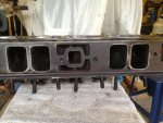
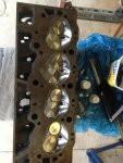
Stringer repair

Scott Danforth

Grumpy Vintage Moderator still playing with boats
Staff member
Joined
Jul 23, 2011
Messages
47,496
was looking for some Chev BB aluminium heads for another 556 ci short block I was putting together.
Thought I would try and save some weight approx. 35kg saving per pair between iron and aluminium
came across 2 pairs of mercury 525efi heads that couldn't say no too.
bare casting # 843425
right price
good timing
nice to scoop a good deal

remember, the mercury racing heads have a mercury racing only exhaust bolt pattern. you will need to modify the heads to fit any other BBC exhaust.
 

bjf66

Chief Petty Officer
Joined
Dec 6, 2016
Messages
406
scott
yes, I've been told the bottom few bolts are different
I get the heads next week so lets see what the actual difference is and whats required to marry heads, and exhaust
 

Scott Danforth

Grumpy Vintage Moderator still playing with boats
Staff member
Joined
Jul 23, 2011
Messages
47,496
top row should be same, IIRC 3 of the bottom are different
 

bjf66

Chief Petty Officer
Joined
Dec 6, 2016
Messages
406
Picked up both sets of heads tonight
set #1: 900-843425, mercury BBC all good, bare with rocker studs and comp cams push rod guide plates
set #2: 900-843944, ha revision B on head, one of the heads had damaged lost a valve head got mashed into the combustion chamber, when I stripped head down it doesn't look that bad, needs welding but didn't touch the valve seat
valves are 2.25/1.9
set 2 head look like the intake ports are a little larger

layered over BBC exhaust gasket over mercury heads exhaust ports
The 4 bottom holes line up as normal, the top 4 holes need to be drilled to suit standard BBC exhaust bolt pattern
good buy for US$300 for both sets
 

Attachments

  • photo328587.jpg
    photo328587.jpg
    123.8 KB · Views: 0
  • photo328588.jpg
    photo328588.jpg
    142 KB · Views: 0
  • photo328589.jpg
    photo328589.jpg
    135.6 KB · Views: 0

bjf66

Chief Petty Officer
Joined
Dec 6, 2016
Messages
406
Forgot to take picture of the head prior to removing valves, however valve head had dislodged and was sandwiched under exhaust valve while closing and mashed the inlet valve into combustion chamber
managed to tap out the valves and no seat damage apart from large cut in combustion chamber
lucky
 

Attachments

  • photo328590.jpg
    photo328590.jpg
    57.5 KB · Views: 1
  • photo328591.jpg
    photo328591.jpg
    118.5 KB · Views: 1
  • photo328592.jpg
    photo328592.jpg
    89.9 KB · Views: 1
  • photo328594.jpg
    photo328594.jpg
    94.6 KB · Views: 1

Scott Danforth

Grumpy Vintage Moderator still playing with boats
Staff member
Joined
Jul 23, 2011
Messages
47,496
you can weld and blend that gash. the one valve guide sleeve is coming out too. that is the downside to aluminum heads in a boat, they do need to be rebuilt a bit more often.
 

bjf66

Chief Petty Officer
Joined
Dec 6, 2016
Messages
406
Scott
that could of been me when I was tapping out the valve stem as it was locked in there reasonably tight or could of been when the valve broke off and grabbed the valve stem
I tried one of the good 3/8" valve stems into the mashed chambers and the guides seem okay as valve slides up and down

not a lot of information around about these casting #'s
will get the chamber welded and blend as suggested, get guides checked out, drill the headers bolts holes for exhaust, no need to have different exhaust pattern if this can be rectified
came with beehive springs and titanium retainers, 10 degree locks, haven't measured the spring yet at the installed height
However will throw some new valves in there
 

bjf66

Chief Petty Officer
Joined
Dec 6, 2016
Messages
406
dissembled heads
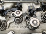
inspected valve train
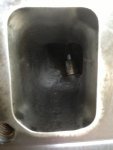
2.25"/1.88" valves don't look to bad once cleaned up
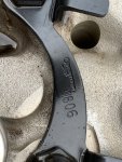
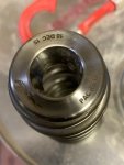
was able to identify the valve spring and retainers
valve springs PAC-1255X beehive/conical single springs 1.45:, installed @ 1.95" with 170 lbs on seat, which can be used with up to 0.700" lift cam,
Both the turbo cams are 0.610" and 0.650" lift @ 1.70" rockers
titanium retainers: Pac R513
10 degree locks
measure installed height and all valves measure within 10lb of each other

so at worst will replace:
16* valves
16* springs
2* titanium retainers
16* 10 degree locks

At best
2* titanium retainers (can purchase singles)
16* 10 degree locks
1* 2.25" inlet valve x 5.218" long (standard length)
1* 1.88" exhaust valve x 5.418" long (0.100" longer)


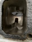
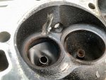
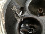
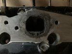
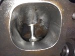
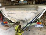
cleaned up the damaged head with gash in combustion chamber, managed to grind off the the aluminium that was damaged exposing the gash, doesn't appear to be that bad and is away from the valve seat
dropped head off at aluminium welder/fabricator who built the aluminium fuel tanks for me, should get the head back next week, then we can go form there and see whats needed, may get away with just blending the combustion chamber and possibly replacing one of the K-lines

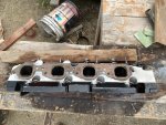
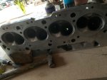
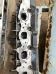
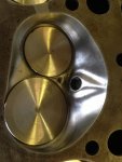
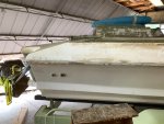
cleaned up the good head yesterday, used oven cleaner, brake clean and WD40, managed to get all the gunk off
head looks good
ports have been cleaned up previously with light porting

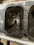
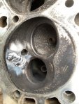
there is some pitting around 2 exhaust ports, maximum 0.060" deep,
do you think this needs to be filled/welded or could use JB weld (500 degree F constant temperature) to fill
interesting its only on 2 ports
interested in whats been done successfully previously?


I don't know the history of head whether they were run in salt water and fresh water although there no corrosion on inside of water passages
assuming there was no closed water cooling
However I will be running closed water cooling system so imagine this problem will not be as severe
 

Attachments

  • photo328844.jpg
    photo328844.jpg
    79.4 KB · Views: 1
  • photo328845.jpg
    photo328845.jpg
    66.5 KB · Views: 1
  • photo328846.jpg
    photo328846.jpg
    58.7 KB · Views: 1

Scott Danforth

Grumpy Vintage Moderator still playing with boats
Staff member
Joined
Jul 23, 2011
Messages
47,496
have the ports welded up when you get the combustion chamber welded.
 

bjf66

Chief Petty Officer
Joined
Dec 6, 2016
Messages
406
yes ports and chamber welded
not sure what the valve seats are made of suppose should try and ID them first before talking to the cylinder head machinist to ensure we put back the correct seat material

purchased some new valves spring PAC-1255X, although the valve springs I took out measure up okay at 175lb @ installed height of 1.95"
however needed to get 2 springs and retainers, which cant source locally.
will have to wait until USA PAC opens after lock down to get order in for 2 titanium retainers and 2 more valve springs
any way no drama keep going with boat
 

Attachments

  • photo329291.jpg
    photo329291.jpg
    122.2 KB · Views: 0
  • photo329292.jpg
    photo329292.jpg
    126.6 KB · Views: 0

Scott Danforth

Grumpy Vintage Moderator still playing with boats
Staff member
Joined
Jul 23, 2011
Messages
47,496
FYI, it helps to polish the chambers, so you have incentive to do that work anyway while you wait for the parts.........
 

bjf66

Chief Petty Officer
Joined
Dec 6, 2016
Messages
406
scott yes agreed, already polished a few iron head castings
these are the 990 rectangle port heads i put on the 402ci BBC
however metal comes off a little quicker with aluminium
 

Attachments

  • photo329295.jpg
    photo329295.jpg
    130.7 KB · Views: 1
  • photo329296.jpg
    photo329296.jpg
    170.1 KB · Views: 1
  • photo329297.jpg
    photo329297.jpg
    186.1 KB · Views: 1
  • photo329298.jpg
    photo329298.jpg
    142.7 KB · Views: 1
  • photo329299.jpg
    photo329299.jpg
    201 KB · Views: 1

bjf66

Chief Petty Officer
Joined
Dec 6, 2016
Messages
406
Exhaust and mufflers setup.
thought I would have a look at how the 4" exhaust pipes would sit now and then fabricate the inside exhaust to where I want the pipes to exit
So looking for some inspiration in determining the position of the exhaust/muffler setup for 22 ft boat
the BBC + turbo (under hatch) is fitted off the transom with inline Z-drive, crash gearbox behind motor
the rear deck/cap slopes down to transom and as my hatch is off the transom approx. 24", was thinking would run the pipes up from inside engine bay through rear deck and then elbow back to follow deck profile and then hang some gibson mufflers i have here

Understand this is a little different setup, however looking for any photos of exhaust pipes coming up through rear deck as opposed coming out of transom
anyone got anything to share
I'll post photo of the rear deck deck setup in few hours after i clear the crap of the boat

first some photos of the boat and transom and rear deck
 

Attachments

  • photo329379.jpg
    photo329379.jpg
    114.7 KB · Views: 1
  • photo329380.jpg
    photo329380.jpg
    111.8 KB · Views: 1
  • photo329381.jpg
    photo329381.jpg
    94.5 KB · Views: 1
  • photo329382.jpg
    photo329382.jpg
    105.2 KB · Views: 1

bjf66

Chief Petty Officer
Joined
Dec 6, 2016
Messages
406
now the mock up with 4" pipes and mufflers
off centre 6" either side

It's a large hoke only want to cut once
thought i would ask the resident experts on what they thought??
please send comments
 

Attachments

  • photo329383.jpg
    photo329383.jpg
    118.5 KB · Views: 1
  • photo329384.jpg
    photo329384.jpg
    110.9 KB · Views: 1
  • photo329385.jpg
    photo329385.jpg
    96.6 KB · Views: 1
  • photo329386.jpg
    photo329386.jpg
    104.5 KB · Views: 1

bjf66

Chief Petty Officer
Joined
Dec 6, 2016
Messages
406
well after deep contemplation while knocking back a few beers on saturday thinking what and how to do this routing of the exhaust pipes, decided to get up early on sunday and cut a few holes in the rear deck and will bring the pipes out there as opposed to through the transom

had some 4" x 15" 316 stainless 0.80" here and used a 90 degree storm water fitting to mock up proposed exhaust tails and to support muffler
 

Attachments

  • photo329592.jpg
    photo329592.jpg
    115.5 KB · Views: 0
  • photo329593.jpg
    photo329593.jpg
    93.5 KB · Views: 0
  • photo329594.jpg
    photo329594.jpg
    92.1 KB · Views: 0

Scott Danforth

Grumpy Vintage Moderator still playing with boats
Staff member
Joined
Jul 23, 2011
Messages
47,496
remember, the sweeping elbows on the exhaust are not as tight a bend as PVC. you may end up with ovals where you have your round holes.

I would run a brace from the end of the mufflers back to the transom. would hate for you to be pounding in some chop and loose a muffler.
 

bjf66

Chief Petty Officer
Joined
Dec 6, 2016
Messages
406
originally i was thinking the exhaust tails/pipes after the come through the deck of boat could be dry no cooling water

But then thought may need to double skin the exhaust to get some cooling as pipe goes through deck
Therefore not sure whether its possible to put a cooling ring between the 4" exhaust pipe and the deck
could make this 150mm dia x 30-50mm deep (deck at rear is 20mm thick), this would have water continuously flowing through to cool the pipe around the deck

any thoughts on whether this would work ??
excuse my rough sketch
 

Attachments

  • photo329595.jpg
    photo329595.jpg
    76.4 KB · Views: 0

Scott Danforth

Grumpy Vintage Moderator still playing with boats
Staff member
Joined
Jul 23, 2011
Messages
47,496
from a reversion point, you only need to run jacketed to the turbos

from a heat point, you may want to run jacketed to the muffler.
 

bjf66

Chief Petty Officer
Joined
Dec 6, 2016
Messages
406
scott
yes there will be a round plate which will be welded to the 90 degree bend and bolted through the deck, and then a saddle support bracket back towards muffler end

do you think i could get adequate cooling of the pipe if I fabricated cooling ring between deck and pipe, and had the rest of pipe outside of hull dry?
cheers
 
Top