Trim Switch Resistance?

spinfly

Cadet
Joined
Mar 28, 2012
Messages
16
Okay, I'm back with an isolated problem on my motor trim problem (I posted the "ConFUSED" wiring & fuses thread last week). And you guys have gotten me a long way this weekend (actually over the course of a couple hours!) Thank you again!

(1996 Suzuki DT40 remote controls)

When using my multimeter to test Ohms:

1) I have the power disconnected from the battery.
2) I think I've narrowed the problem down to the actual toggle switch on the throttle lever.
3) There are 3 wires coming from the toggle switch: gray - 12+; pink - trim down; light blue - trim up. (Please correct me if I'm wrong)
4) I've removed a tiny portion of the insulation from each of the three wires a couple inches from the toggle switch.
5) TRIM UP:
a) When I probe the gray (middle) and pink (trim down) wires WITHOUT pressing the up switch, i get a reading of infinite resistance (1). As it should be, right?
b) When I probe the gray and pink wires while pressing the trim down button, I get 000 resistance. As it should be, right (perfect contact)?
6) TRIM DOWN:
a) When I probe the gray (middle) and light blue (trim up) wires WITHOUT pressing the up button, i get a reading of 000. Doesn't this mean there is a short in the switch?
b) When I probe the gray and light blue wires while pressing the trim up button, I get 000 resistance, as expected.

So... Bad Trim Toggle Switch?

I even took apart the toggle switch and got the same results when probing the respective contacts.

Or am I missing a fundamental on relay wiring/switches?

Thank you again!
 
Last edited:

Silvertip

Supreme Mariner
Joined
Sep 22, 2003
Messages
28,762
Re: Trim Switch Resistance?

You should set the meter to read voltage rather than resistance. Connect the battery and measure voltage from the center terminal on that terminal, power is getting to the switch. Then probe each of the end terminals while activating the switch both ways. In one direction you should read 12 volts and the other 0. If you read 0 in either or both positions the switch is bad.
 

spinfly

Cadet
Joined
Mar 28, 2012
Messages
16
Re: Trim Switch Resistance?

Thank you for the reply Silvertip! I'm sorry to say I didn't understand your last two statements; they seem contradictory, with a "0" reading being acceptable in 1 of 2 positions on the switch, then stating a reading of "0" in either position is unacceptable.

Not saying your understanding of testing this switch is incorrect, I just couldn't follow which test results were acceptable and which were not based on those two statements. I think I have a good understanding of resistance, which is why I went to the trouble of narrating my test and results and was seeking confirmation in that respect. My apologies if I misunderstood good instructions.

Nonetheless, I replaced the switch and am getting the proper readings now. But apparently my wiring problem is multi-faceted....

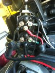
The trim is still not working. I have a two-wire trim motor. Disconnected the blue and green wire from the up and down trim relays (that go to the motor), connected them to 12v, motor works fine; ran fully up and fully down. So, me thinks i need to test each individual relay. My Service Repair manual provides instructions for doing this, except they refer to terminals "1", "2", "3", and "4", but none of the terminals are labeled on the trim relays. How do I go about testing the relays then? (please see attached photo)trim relays.jpg

Also, I have a short somewhere on the WHITE wire that houses a 20A fuse on the starboard side of the motor. This WHITE wire starts at the lower post of the STARTING relay and can be traced all the way to the ignition switch at the control box. With 12v+ connected, the fuse blows immediately when I reconnect the fuse holder with a new fuse. Anybody with experience with this? My gut is telling me this is the real problem, but I don't know the best way to isolate this problem since I can't connect the fuse w/o it blowing. Seems that testing continuity would identify the issue, but it also seems that more people are more familiar or at least prefer testing voltage.

If it's advisable to split these problems in to two threads, would be happy to do so; not sure if it helps to have all the info in one thread. Thanks again guys.
 
Last edited:

Silvertip

Supreme Mariner
Joined
Sep 22, 2003
Messages
28,762
Re: Trim Switch Resistance?

Without creating a bunch of "here's how diagrams" switches can be checked in either of two ways. Resistance as you tried to do or voltage. Unfortunately, unless you understand the TOTAL circuit you cannot reliably check a switch by resistance unless it is OUT OF THE CIRCUIT. To check the switch by measuring resistance you put one probe on the +12 (common) terminal of the switch. You then probe either the up or down side of the switch. It should show open circuit (infinity) until you activate the switch. Same process for the other function. If the switch shows infinity when activated that function is not working. If it shows closed circuit (zero) when the switch is NOT pressed the switch is also bad. With power applied, first check for 12 volts on the COMMON terminal fo the switch. Then probe both the up and down side of the switch. Should read zero. Activate the swtich in either direction and measure the applicable terminal. Should show 12 volts. If not. Bad switch,

As for relays -- you need to understand the configuratin of the relay. All relays have a coil. Again. It needs 12 volts in and ground to energize. You then measure voltage at the various normally open and normally closed terminals. Without a schematic you have little chance of testing the relay.
 
Joined
Feb 17, 2012
Messages
2,906
Re: Trim Switch Resistance?

take any 12vdc device (i use a lamp that use to run of a cig lighter socket) crimp on 2 female spades and plug in where the fuse goes if its shorted the light comes on then i can unplug other items and wiggle wires when the light goes off or real dim then fuse is no longer shorted. works great with a 12v buzzer but drives the wife nuts.
internet search for suzuki wire colors white says "power wire" so you might have to unplug a few things to narrow it down (did you open controller to get at trim and tilt buttons? any chance you nipped one when you put it back together)

silvertips is correct about the way you are testing. if you test for resistance on a switch thats still in circuit you can get a miss read as the load or line could be shorted. always best to find a ground for one lead and then use the other to test the positives.

picture doesnt give enoght detail it looks like a 6 wire relay. isnt there a wiring diagram on the inside of the cover?.......if not draw the wires and posts of the relays and tell us where they are connected and we can proberly work out the post numbers for you.
 

hrdwrkingacguy

Petty Officer 1st Class
Joined
Mar 9, 2010
Messages
368
Re: Trim Switch Resistance?

In general you can have voltage across an air gap(a contact or a switch) or an energized load(a motor, or light, or horn) and a line of potential to ground...when you go from the center to the top or bottom and the switch is in the middle, you should have voltage from the center to the bottom, and the center to the top...when you close the switch the air gap closes and you are on the same line of potential so you will read 0(or a voltage generated by resistance in the contact)...so 12vdc from center to the top then push the trim up, if it goes to 0 the switch is good, same thing from the center to the bottom when you trim down...:eek:

Voltage from the top to the bottom means problems...
 

Silvertip

Supreme Mariner
Joined
Sep 22, 2003
Messages
28,762
Re: Trim Switch Resistance?

In general you can have voltage across an air gap(a contact or a switch) or an energized load(a motor, or light, or horn) and a line of potential to ground...when you go from the center to the top or bottom and the switch is in the middle, you should have voltage from the center to the bottom, and the center to the top...when you close the switch the air gap closes and you are on the same line of potential so you will read 0(or a voltage generated by resistance in the contact)...so 12vdc from center to the top then push the trim up, if it goes to 0 the switch is good, same thing from the center to the bottom when you trim down...:eek:

Voltage from the top to the bottom means problems...

While you are correct in your description, this is not a good technique since the op is trying to prove/disprove the switch. If there is an open circuit the meter will not read so it would tend to indicate a bad switch when the problem is really elsewhere in the circuit. Make the voltage measurements to ground.
 

hrdwrkingacguy

Petty Officer 1st Class
Joined
Mar 9, 2010
Messages
368
Re: Trim Switch Resistance?

While you are correct in your description, this is not a good technique since the op is trying to prove/disprove the switch. If there is an open circuit the meter will not read so it would tend to indicate a bad switch when the problem is really elsewhere in the circuit. Make the voltage measurements to ground.

I guess I have a hard time seeing something from the perspective of someone this stuff isn't second nature to...

If you have 12vdc to ground at the center terminal and a load at the other end, then everything I said is true...I see your point though a wire break up stream and you get nothing and a wire break downstream you get nothing...:eek:

If it we me trying to just see if the switch works, I would go from the center to the top and bottom on dc volts, if it works as expected and it goes to 0 on a switch closure switch is good...If its 12vdc to ground at the center and doesn't go to 0 I would move to the top and bottom terminal to ground and see what happens when the switch closes...If it goes to 12vdc the switch is good and its time to move toward the relay...no 12vdc at the center terminal and its time to go backwards toward the fuses or where the center wire comes from...
 
Joined
Feb 17, 2012
Messages
2,906
Re: Trim Switch Resistance?

have you worked out the relays yet? im slightly color blind for a electrician so the 2 wires on the right of the picture both look green but the paint on the terminal looks blue. if that is correct then the 2 on the left should both be grounds and joined together. if this is correct then the relays should have one normally open set of contacts and one normally closed set of contacts.
both relays supply the negative until one is active then it changes from supplying negative to supplying positive to the motor if the relays do not click then test the 2 small leads that are moulded into the side of the relay black is ground the other one is postive from the switch you just replaced. if one click but does not change state then that relay is proberly bad and may be breaking but not making the circuit.
 

hrdwrkingacguy

Petty Officer 1st Class
Joined
Mar 9, 2010
Messages
368
Re: Trim Switch Resistance?

It looks to me like its two seperate SPST relays with each having a wire for the coil + and - and a set of contacts...:eek:
 

trendsetter240

Lieutenant
Joined
Jun 22, 2009
Messages
1,458
Re: Trim Switch Resistance?

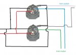
The joining plate is the input signal. There should be two switches to actuate the trim; one on the control box and another on the side of the outboard.

So two inputs to activate the relay, one (the red) for power source and a fourth (the black) for the power out to the trim pump. Notice the red wire is joined between the two relays...one power source for both.
 
Joined
Feb 17, 2012
Messages
2,906
Re: Trim Switch Resistance?

i hate to argue but theres 4 terminals and 2 leads (look at the top right of the relay and you will see the 2 leads one is black one is white with stripe) thats the power to the relay coil. the reds are joined like you say and so are the blacks. the original poster also says that the trim wires are blue and green and judging by the parts sites they sell them as either a up or a down the diffrence being which terminal they painted which color. plus it makes electrical sense that if you want a reversable circuit using 2 relays thats how you would do it.
suzuki part# 38410-94552 for the up at about $118 (would test the hell out of it before i payed that much). what ever i dont think the guys has a problem other than a short somewhere thats taking out the fuse for the power supply wire to the controller which is proberly the same power that is used for tilt and trim.
 

hrdwrkingacguy

Petty Officer 1st Class
Joined
Mar 9, 2010
Messages
368
Re: Trim Switch Resistance?

There are two wires with heat shrink plastic on each relay at 1 o'clock, that looks like the power to the coil...Is the coil negative connection the green wire or is it grounded through the body of the relay or is there something I don't see...If the green is the negative and the wires at 1 o'clock are the coil then they are a pair of spst relays if the green is part of the contacts they are spdt I don't see how they could be dpdt and have a trim up and trim down as you would need two relay coils...:eek:
 

Silvertip

Supreme Mariner
Joined
Sep 22, 2003
Messages
28,762
Re: Trim Switch Resistance?

All this speculation on the relay construction could be settled Googling the part number & manufacturer off the relay itself, or by looking at a diagram for the motor in question. Even posting a picture of the relay would help some. But it takes two terminals to energize the coil. There will typically be three other terminals for one set of relay contacts (one common, one, N.O. and one N.C.). On many relays there will be another set but only one coil. It is possible the relay has a common and either a N.O. or N.C. set of contacts in which case there will be total of four terminals (or six if there is second set of common and N.O. or N.C. contacts.
 

spinfly

Cadet
Joined
Mar 28, 2012
Messages
16
Re: Trim Switch Resistance?

Fellas, I'm sorry for the wild goose chase. My inexperience prevented me from tackling this problem in the right order. Trim relays are fine. (BTW - Trim motor is just 2 wire: 1 dark blue, 1 green. There is a small black wire that goes in with the light blue wire for the UP relay, and a sm blk wire that goes in w/ the pink wire for the DOWN relay. Both of these black wires are grounded to the relay "frame", which is grounded to the starting relay (if I remember correctly) on the starboard side of the motor. And red wires are bridged between both relays, as well as the black wires.) I must admit you guys lost me a little on your relay discussion, but I defnitely learned some things from you on the subject. It was not in vain!

The problem has been solved...with a rather anti-climactic ending. Turns out, as some of you have mentioned, the 20A fuse circuit hosts the ignition and trim function. Via some random prodding and investigating, I took the rectifier out of the housing, and the back was ever-so-slightly cracked.....Hmmmm.......So i disconnected the rectifier, put in a new fuse........Presto! The fuse did not blow; motor now cranks at the ignition switch, and the trim up and trim down are fully working.

It's all coming together now.... Seller of boat did NOT have a battery for the boat, he jumped it from his lawnmower (if this isn't redneck, I don't know what is!!!:facepalm:...so, what does that make me!) I dug around here in the electrical section and learned that running the motor without a battery will pop the rectifier (Nov. 2010). 2 points for Silvertip!!!

New rectifier is on its way. I will post up if further problems ensue. For anyone w/ similar issues...If the motor won't crank, fix that first! Everything else just might take care of itself! Either way, these helpful guys will offer tons of great info and get you pointed in the right direction. Thank you all!:cool:
 

Silvertip

Supreme Mariner
Joined
Sep 22, 2003
Messages
28,762
Re: Trim Switch Resistance?

So checking for "voltage" at the trim switch rather than checking for "resistance" was the right troubleshooting approach eh? Sorry -- couldn't resist. Does a circuit have power is always the first check. If it does, then go after other things that don't work. no gauges, no trim, and no start are generally the result of a popped engine compartment fuse.
 

spinfly

Cadet
Joined
Mar 28, 2012
Messages
16
Re: Trim Switch Resistance?

Touch?. But I didn't know I wasn't dealing with 2 isolated problems at the time. Didn't know boats were wired that way. Only discovered that was the case when both problems vanished at the same time. Shouldn't have compartmentalized everything in my mind. Like I said...inexperience.
 
Joined
Feb 17, 2012
Messages
2,906
Re: Trim Switch Resistance?

nice to see ya got it fixed that what matters in the end. good spot on the rectifier that wouldnt have been my first guess of where to look for it.
 
Top