


I have a 1996 Mercury 200 EFI. My tachometer started to act crazy. It jumps around sometimes and is unreliable. Sometimes it appears to show the right reading, but then sometimes spikes depending on how much power I give it.
Also, my cranking battery is being drained while the boat sits. I disconnect the battery when I put the boat up to keep it from draining. When I reconnect the battery, there are sparks as if the motor is on.
From everything I've read, it appears I have a bad rectifier/regulator(s). I wanted to see what I could do before spending $300 to replace both of them. I realize that is probably the easiest fix, but definitely the most expensive.
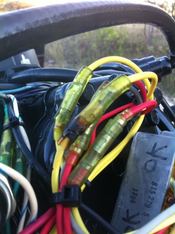
In the attached picture, you can see that one of the yellow wire connectors that is connected to the upper rectifier is burned. That rectifier is also the one that the tach is connected to. Could replacing the connector possibly help?
Both rectifier/regulators appear to be the originals with the clear potting. Neither circuit board in either regulator appears damaged or melted like I hear some people have experienced.
I tried ohmmeter tests on both rectifiers. I disconnected all the wires before testing. Both rectifiers had essentially the same results. Three of the tests came back within the proper range, but one didn't. I'm not sure what this tells me, however, because I'm no electrical guru. Here were the results:
Negative to Yellow, Positive to Large Red = 40 (should be between 100-400)
Negative to Large Red, Positive to Yellow = 100K (should be between 40K to infinity)
Negative to Yellow, Positive to Ground = 20K for one 15K for other (should be between 10K to infinity)
Negative to Ground, Positive to Gray = 19K for one 15K for other (should be between 10K to 30K)
Any help would be appreciated. Thanks.
Also, my cranking battery is being drained while the boat sits. I disconnect the battery when I put the boat up to keep it from draining. When I reconnect the battery, there are sparks as if the motor is on.
From everything I've read, it appears I have a bad rectifier/regulator(s). I wanted to see what I could do before spending $300 to replace both of them. I realize that is probably the easiest fix, but definitely the most expensive.
In the attached picture, you can see that one of the yellow wire connectors that is connected to the upper rectifier is burned. That rectifier is also the one that the tach is connected to. Could replacing the connector possibly help?
Both rectifier/regulators appear to be the originals with the clear potting. Neither circuit board in either regulator appears damaged or melted like I hear some people have experienced.
I tried ohmmeter tests on both rectifiers. I disconnected all the wires before testing. Both rectifiers had essentially the same results. Three of the tests came back within the proper range, but one didn't. I'm not sure what this tells me, however, because I'm no electrical guru. Here were the results:
Negative to Yellow, Positive to Large Red = 40 (should be between 100-400)
Negative to Large Red, Positive to Yellow = 100K (should be between 40K to infinity)
Negative to Yellow, Positive to Ground = 20K for one 15K for other (should be between 10K to infinity)
Negative to Ground, Positive to Gray = 19K for one 15K for other (should be between 10K to 30K)
Any help would be appreciated. Thanks.
 I'm just not sure where, exactly, to hook each side of the ammeter to.