Tach wiring help...attached pics

Tinlizzy

Petty Officer 2nd Class
Joined
May 7, 2007
Messages
121
Greetings,
I am in need of a bit of help..I am in the process of identifying wires/rewiring on the boat. The owner before me seems to have a bit of a mess here with wires. I am onto the tach wires and trying to figure these out. I have attached photos. This is for a 1971 115 hp inline merc.

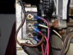
First pic: Is a shot of the switch box assembly on the distributor side. The second terminal down from the top has two wires, a white and a red. The red wire was added to run from the motor to the ground terminal on the tach. The white attaches to the distributor.

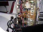
Second pic: This shows the red wire running out of the engine to the tach.

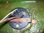
Third pic: This shows the back side of the tach. The black wire coming off of the back is spliced to the red wire, for the ground.

The question is, why do I need this red wire grounded from the side of the switch box assembly and not a common ground from the battery? Does this tach require this from the distrib? thanks in advance! :)
 

Attachments

  • DSCN10061.JPG
    DSCN10061.JPG
    82.2 KB · Views: 0
  • DSCN10071.JPG
    DSCN10071.JPG
    95.2 KB · Views: 0
  • DSCN10102.JPG
    DSCN10102.JPG
    48.2 KB · Views: 0

Texasmark

Supreme Mariner
Joined
Dec 20, 2005
Messages
14,559
Re: Tach wiring help...attached pics

Can't make much out of your pics, not familiar with engine and all, but a tach (of today.......... at least, don't know about that year) uses 12v from the ign switch to run the electronics, a tach rpm signal from the engine, sometimes a separate light and power source (from the boat's light switch.....I think I see that in the 3rd pic) and a ground wire.

You could probably probe and do a visual on the engine to figure out which wires are which, but on the tach, hard to say if there are no markings on the rear of it.

Sorry I can't do better,
Mark
 

Tinlizzy

Petty Officer 2nd Class
Joined
May 7, 2007
Messages
121
Re: Tach wiring help...attached pics

Thanks for the reply.

I know the brown wire is the tach sender from the switch box. I just cant figure out the reason why they ran a ground from the side of the switch box all the way to the tach?:confused: Instead of using the ground out of the back of the control box with the white/brown for the tach hookup.
 

jtexas

Fleet Admiral
Joined
Oct 13, 2003
Messages
8,646
Re: Tach wiring help...attached pics

The white wire, from the switch box to the distributor - any idea what it's function is? if it's not connected to engine block ground, then the tach GND isn't either - and if the tach is working now, then it must require a ground other than the normal battery negative "common ground" (at least, in its current installation). But if the white wire is grounded, then logically it must be the electrical equivalent of the control box ground............disclaimer: I'm not speaking from experience with your particular motor...........
 

Tinlizzy

Petty Officer 2nd Class
Joined
May 7, 2007
Messages
121
Re: Tach wiring help...attached pics

J Tex,
That is correct, the red wire is serving as a ground. But why would they just not use the one from the control box is the question? :confused: They went through an awful lot of work to run that wire. The black wire (ground) from the control box is a live ground...I tested it. But it is not connected to anything, just dangling under the dash.....


This all makes no sense....before I remove that wire, and use the ground from the control box, I just want to make sure it does not serve any other purpose besides being a ground? And I will not damage the switch box somehow.
 

ricksrster

Commander
Joined
Jun 19, 2005
Messages
2,022
Re: Tach wiring help...attached pics

I think your tach wire is on the wrong side of the switch box. In the diagram it is shown under the green + coil wire.


35.jpg
 

Tinlizzy

Petty Officer 2nd Class
Joined
May 7, 2007
Messages
121
Re: Tach wiring help...attached pics

Thats correct rick, the brown sending wire for the tach is hooked up correct. The question is the ground. which is the red wire coming off of the side of the switch box in the first pic.
 

ricksrster

Commander
Joined
Jun 19, 2005
Messages
2,022
Re: Tach wiring help...attached pics

I don't think that white wire on the switch box is a ground. I would use the one from the control. Is this an old style tach? The new ones connect the send wire to either yellow at the rectifier.
 

Bill Adkins

Seaman
Joined
Sep 27, 2006
Messages
68
Re: Tach wiring help...attached pics

I just installed a tach on a 1971 1350 and it went a bit differently. The wire for the tach take off was from the right side driving direction of the switch box on the motor. The wires I used were from the throttle control assy, they actually come out of the front of the throttle assy and run to the tach assy. Thet are a factory setup, the gague package had really good pictures and the manual I bought from I boats had exellent pictures of all applicable wireing situations.
Bill
 

jtexas

Fleet Admiral
Joined
Oct 13, 2003
Messages
8,646
Re: Tach wiring help...attached pics

still unclear about something........is the tach working now?

Didn't see an answer to my question, what's the white wire connected to your red ground wire? Should be pretty easy to determine if that post with the red wire is a common ground wire same as the control box black. If it is and if the tach works, isn't that all you need to know?
 
Top