homemade power trim relay

Status
Not open for further replies.

dsujen

Petty Officer 1st Class
Joined
Oct 16, 2004
Messages
252
I have a 1986 110hp vro evinrude without power trim. Just purchased a power trim for it on ebay. It came with the limit switch that mounts on the side of the motor bracket and 2 big wires(a blue one and a green one). I put the blue and green wires directly on a car battery and the cylinder went up, Then I flipped them and it went down. It needs solenoids to get it to run. I was wondering if there is some type of solenoid and toggle switch kit I could mount on my boat to get it to run the way it was designed. Or if I could just use 2 cheapo starter solenoids and a 3 position toggle switch to get it to work.
 

Texasmark

Supreme Mariner
Joined
Dec 20, 2005
Messages
14,562
Re: homemade power trim relay

The motor changes direction by changing the direction of current through it. So you have to be able to alternately apply 12v or ground to each lead and if you are applying 12v to one motor lead with the control switch in one direction the other motor lead needs to be grounded then the process is reversed when the control switch is reversed.

A SPDT spring loaded toggle (On-Off-On) switch would be required and two DPDT relays. Your conventional solenoid is SPST.

If I could figure out how to send you a hookup schematic I could make on a notepad I would. Basically you have to put power on (the whole circuit) when desired, in the direction desired and that power needs to hook the motor to 12v and gnd in the direction desired to obtain motor movement in the direction desired.

Not rocket science, but a schematic would make it much more easily understood and much less wordy.

Mark
 

tommays

Admiral
Joined
Jul 4, 2004
Messages
6,768
Re: homemade power trim relay

? usally at least on a merc pump blue would run the pump UP and green DOWN
Is there no black ground wire ?


Tommays
 

PondTunes

Petty Officer 1st Class
Joined
Jun 7, 2007
Messages
387
Re: homemade power trim relay

I put the blue and green wires directly on a car battery and the cylinder went up, Then I flipped them and it went down.

Sounds like its just a simple current reversing circuit.

+ on blue and - on green = cylinder up.
- on blue and + on green = cylinder down.

trim.jpg


When the switch is pressed up a ground is sent over to the left relay's terminal #86. This closes the connection between #87 & #30. sending 12v to the blue trim wire and a ground to the green trim wire. Since the second relay is not energized then terminal #87a is connected to #30 and thus grounded.

When the switch is pressed down the cycle reverses energizing only the right relay.

Tada.
 

dsujen

Petty Officer 1st Class
Joined
Oct 16, 2004
Messages
252
Re: homemade power trim relay

I bought 2 starter solenoids for a car. They have 2 big terminals, one small terminal, and the frame is ground. I also bought an on-off-on toggle switch. Can I use this set up? If not, what kind of relays do I need and where do I get them cheap?
 

wire2

Lieutenant Commander
Joined
Jun 25, 2007
Messages
1,584
Re: homemade power trim relay

PondTunes, your circuit will theoretically work, unfortunately, that type of automotive relay is good for 30A at most. Trimming out on plane will take 50-60 A. They won't last.

Dsujen, place an ohmmeter from the motor case to the green and/or blue wire. 3-4Ω?

If so, connect a wire from the motor case to battery ground, then try +12v to EITHER blue or green, (NOT both at once).
I'm 85% confident it'll work. Then you can use the starter relays you bought to power blue and green for up/down.
 

dsujen

Petty Officer 1st Class
Joined
Oct 16, 2004
Messages
252
Re: homemade power trim relay

No continuity between either wire with ground. To get it to move I have to put the green on the + and the blue on the - on a battery. To get it to go the other way I just have to put the blue on the + and the green on the - on the battery. Where did you get and what kind of relays are in your schematic?
 

wire2

Lieutenant Commander
Joined
Jun 25, 2007
Messages
1,584
Re: homemade power trim relay

DANG! I was so expecting that to work.

The numbers in PondTunes' schematic are standard automotive relays, but as I mentioned, they're rated at 30 A or less.

You need to get 12 v coil SPDT (Single Pole, Double Throw) relays good for at least 50 amps.

I'm on my way to the cottage now but if you haven't found some by Tuesday, I'll try to find a source and part #.
 

PondTunes

Petty Officer 1st Class
Joined
Jun 7, 2007
Messages
387
Re: homemade power trim relay

PondTunes, your circuit will theoretically work, unfortunately, that type of automotive relay is good for 30A at most. Trimming out on plane will take 50-60 A. They won't last.

Thats odd, the power trim on my 90 horse Johnson uses standard automotive style relays and works fine. Looking in the iboats store under Relay almost every single trim relay is the 30a model. Even the add-on power trim units say they only draw 5-20 amps.

Just use wire of equal size to hook up the relay's and you should have no problems. Or if you want to spend three times as much you can probably find 85 amp relay's from stinger or someone that deals in battery switching devices.
 

guy74

Senior Chief Petty Officer
Joined
Jul 12, 2007
Messages
794
Re: homemade power trim relay

I use standard (bosch style as the are known in the heavy equipment industry) on my motor. They are rated for 30 amps continous current. I replaced them both after one of the OEM relays failed, they have worked fine for 4 years now. I think you will be ok with the setup that PondTunes recommended.
 

PondTunes

Petty Officer 1st Class
Joined
Jun 7, 2007
Messages
387
Re: homemade power trim relay

Thats pretty much the same setup as using 2 individual relays and should work just as well. Would be a little simpler to wire too.
 

Texasmark

Supreme Mariner
Joined
Dec 20, 2005
Messages
14,562
Re: homemade power trim relay

Dsujen, count the wires from each relay in the schematic. You have to have 3 things happen and a conventional solenoid only does two It's a coil driven SPST switch. (Single Pole Single Throw

You have to apply 12v and ground (two separate switches...relay 1) and the control wiring.....blue wire gets 12v green ground.

Then you have to reverse both 12v and ground (different set of two separate switches...relay 2) and provide the control power so that this time green gets 12v and blue ground.

That's why you need 2 DPDT (coil driven) relays of the proper amperage. Double Pole Double Throw.

Mark
 

wire2

Lieutenant Commander
Joined
Jun 25, 2007
Messages
1,584
Re: homemade power trim relay

Thats odd, the power trim on my 90 horse Johnson uses standard automotive style relays and works fine. Looking in the iboats store under Relay almost every single trim relay is the 30a model. Even the add-on power trim units say they only draw 5-20 amps.

Ok, I just realized we're talking outboards?
I was thinking I/O. My bad.

Dsujen, if you got the HD solenoids cheap, get 2 more and it will work fine. You just need to power 2 at once to ground & 12v one way, the other 2 at once for the other way. I'll email you a schematic if you need.

Or, since your current is less than 30 A, the Bosch relays will work also, just follow PondTunes' schematic above.
 

jtexas

Fleet Admiral
Joined
Oct 13, 2003
Messages
8,646
Re: homemade power trim relay

you could do it with a single DPDT switch:

motorswitchwiring.jpg
 

Texasmark

Supreme Mariner
Joined
Dec 20, 2005
Messages
14,562
Re: homemade power trim relay

That'll work and they make 30 amp DPDT switches.....W.W. Grainger is a place to start looking.

Mark
 

Texasmark

Supreme Mariner
Joined
Dec 20, 2005
Messages
14,562
Re: homemade power trim relay

Did your home work for you: Note: W.W. are the initials of Mr. Grainger. Do not confuse with the World Wide Web notation "www".

Switch mfgr: Hubbell

Mfgr P/N: HBL223SPMM

W.W. Grainger P/N: 3D545

Grainger Price (2004-2005 catalog 395) $12.59

Ratings:

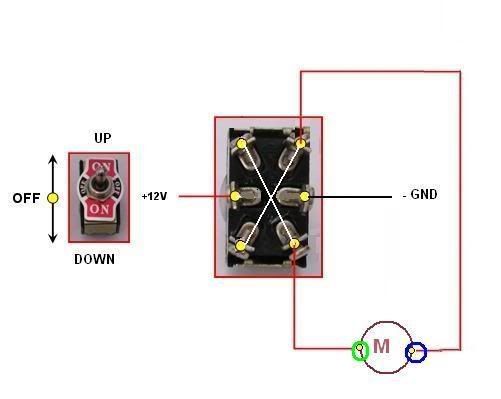
DPDT, Spring loaded, On/Off?On; 6 terminals (Push toggle up or down to activate trim and when finished release toggle and it springs back to center which is OFF.)

Max 250V DC; 3/4 HP........@ 741 watts/hp X3/4 HP = 556 watts/12V = 46 max amps per pole set.......far exceeds the 30 amp criteria. Ought to work for a long time.....be sure and save your invoice so if you need to order another, you will know what and where you got this one.
----------------------
Silicon Rubber Boot (screws on after mounting and covers toggle arm to keep water out of switch:

Hubbel P/N MSB1; Grainger 3JC12; $12 (Ha! costs as much as the switch but you don't want to be without it because water can easily enter the switch mechanism and screw it up in no time.

So for $25 and jtexas' how to hook it up diagram, my man, you are in business.
------------------

Grainger is a wholesale house and is a world wide supplier. Phone number is that of your local merchant; they list no 800#. Get the local yellow pages, or go to www.grainger.com and find your nearest wholesaler.

Ought to be someone you know (if you can't) who can buy electrical/electronic parts wholesale. Usually, if person works for a large OEM manufacturing co, the local Grainger will honor their badge to make purchases.

HTH

Mark
 

tommays

Admiral
Joined
Jul 4, 2004
Messages
6,768
Re: homemade power trim relay

While the simple switch would work i think the LONG LARGE wires needed to reach the dash and back would a downside to think about

Compared to relays close to the motor trim pump that would only need small control wires


Tommays
 

wildmaninal

Lieutenant Commander
Joined
Jul 14, 2007
Messages
1,897
Re: homemade power trim relay

The diagram that JTexas posted works, he posted it on my thread a while back. You don't need solenoids just a bunch of 10 gage wire and jump the wires from one side of the DPDT switch like it shows on the diagram and it should work fine. It sounds like you have the same power trim that I have. I hooked mine up at the driver's console and at the front of the boat.
 

wire2

Lieutenant Commander
Joined
Jun 25, 2007
Messages
1,584
Re: homemade power trim relay

Max 250V DC; 3/4 HP........@ 741 watts/hp X3/4 HP = 556 watts/12V = 46 max amps per pole set.......far exceeds the 30 amp criteria. Ought to work for a long time....

Mark, you've done your homework but I'm afraid there's a few shortcomings in your calculations.

The HP rating of an electrical switch is a measure of the energy that it's capable of interrupting. It takes induction into account but doesn't translate directly into watts and amps at xx volts.

Also, 741 watts is 1 theoretical HP on paper, and is used to compare the energy output of gas or Diesel engines to steam boilers, turbines etc.

In reality, a 1HP electric motor, on a table saw, for instance, will draw 12 amps at 115 volts. That's 1380 watts (if we ignore power factor of an inductive load).
Fractional HP motors are even less efficient.

Have a look at the size of the prongs of the electric plug-in of your clothes dryer. It's rated at 30A, 250V. Now look at the size of the lugs on a common DPDT switch for comparison.
 
Status
Not open for further replies.
Top