Working under the back deck/splashwell

theoldwizard1

Petty Officer 1st Class
Joined
Feb 25, 2014
Messages
341
I have a 2002 Starfire 170 that is going to get splashed for the first time this year, "real soon", but of course there is some maintenance left from last year. The gas gauge quit working.

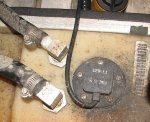
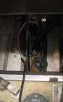
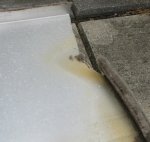
Looking through the access port in the splashwell (not sure what good that really is) I can see the connections for the fuel gauge. It appears that they have 2 male/female spade/faston connections with some vinyl sleeves over them. I am betting the gauge is good and the connections are corroded (seem like every year I have to replace the fuse in the battery compartment because it won't pass current. This year I used Fluid Film on it).

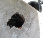
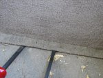
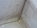
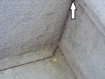
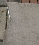
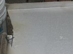
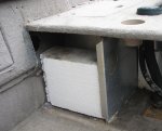
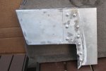
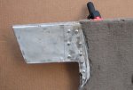
Removing the seat post base on the casting deck (and enlarging the hole) I can see the fuel gauge (the only thing on the tank with wires), but even with these access holes I really can not get in there to do any work ! The plywood base of the casting platform sits on a piece of aluminum. I don't know if that is part of the splashwell or not. Simply removing the plywood layer of the casting platform is not going to help much.

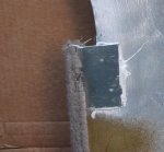
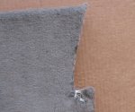
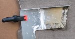
Can anyone tell me how the "face" (vertical) piece of the casting platform is attached ? Of course everything is carpeted and carpeting hides screws very well !

Also any suggestions for what to use as replacement connectors ?
 

laurentide

Lieutenant Commander
Joined
Jul 24, 2011
Messages
1,869
Your boat is "too new" for most of us to know how it's put together. I guess you'll have to pull carpet to see where the fasteners are. For connections I'd use tinned wire with crimped connectors, heat shrink and dielectric grease.
 

GA_Boater

Honorary Moderator Emeritus
Joined
May 24, 2011
Messages
49,038
Didn't we have a Super Fisherman rebuild, Maybe Budski? They are similar to the Starfire.
 

SCStarcraft

Cadet
Joined
Feb 3, 2016
Messages
26
Budski should know. He has a 1995 SFM 170. Wizard, please take pics of you disassembly--I have a '99 Starfire and need to do some rewiring under there. It would be great to learn from your experience!
 

theoldwizard1

Petty Officer 1st Class
Joined
Feb 25, 2014
Messages
341
No Title

Okay. They say a picture is worth a thousands words. Here is a couple thousand !

#1 Reciprocating saws can NOT cut round holes ! Without enlarging the hole I could not get my hand down there

#2 Straight down the hole. Pretty sure that is the fuel level mechanism.

#3 Looking toward the transom.
 

Attachments

  • photo245111.jpg
    photo245111.jpg
    152 KB · Views: 1
  • photo245112.JPG
    photo245112.JPG
    212.1 KB · Views: 1
  • photo245113.JPG
    photo245113.JPG
    200.8 KB · Views: 1
Last edited:

theoldwizard1

Petty Officer 1st Class
Joined
Feb 25, 2014
Messages
341
No Title

More pictures

#1 No screws between the casting deck and this vertical piece. Confirmed by non-visual inspection inside.

#2 Screws connecting that little lip to the floor were removed. Pry bars make the panel move some. Pulled forward about 1/2".

#3 You might no be able to tell, but this picture shows the the vertical panel is IN FRONT of the side panels. Close inspection show no screws along this edge.
 

Attachments

  • photo245110.JPG
    photo245110.JPG
    217.3 KB · Views: 1
  • photo245120.JPG
    photo245120.JPG
    245.1 KB · Views: 1
  • photo245122.JPG
    photo245122.JPG
    214.4 KB · Views: 1
Last edited:

theoldwizard1

Petty Officer 1st Class
Joined
Feb 25, 2014
Messages
341
I am thinking that the panel is now just a friction fit because I can not find any other fasteners. Banging with my fist on the inside had no effect. I am going to try a soft face dead blow tomorrow.

After that ....???? Med-evil ! Some kind of hook underneath and a slide hammer ?
 

SCStarcraft

Cadet
Joined
Feb 3, 2016
Messages
26
Okay. They say a picture is worth a thousands words. Here is a couple thousand !

#1 Reciprocating saws can NOT cut round holes ! Without enlarging the hole I could not get my hand down there

#2 Straight down the hole. Pretty sure that is the fuel level mechanism.

#3 Looking toward the transom.

Thanks so much for the pictures, Wiz. Regarding #2, I haven't had to fool with the fuel level sensor on my Starfire, but it looks exactly like my tractor one that I had to work on. If so, I think the system is essentially an ohmmeter; the sending unit has a float attached to an arm and an electrical contact bearing on a coil. It's a variable resistor. The contact arm (like a distributor point) has a shaft and bushings that are mounted in a stamped steel cage. Over time, sloshing and wear cause the contact point not to make a good connection with the coil. So the gauge (ohmmeter) appears not to work.

All I had to do on the tractor was remove the five seal plate screws, pull the sending unit out and use some pliers to squeeze the stamped cage together so that the contact was better between the point and the coil. It's worked fine since that repair.

Your challenge would be to have enough access to get the sending unit with its long float arm out through the pretty small seat base hole, make the repair, and get it back in, which requires the ability to angle it enough to prevent bending the float arm.

Somebody who has removed a Starfire sending unit can confirm this design or say no, it's entirely different; if so, please ask the mods to delete this post of wrong.

From pictures #2 and #3, it looks like you've been able to get the platform surface removed, and maybe even the splash well (the bilge looks to be visible)? If you have, can you provide a step-by-step for getting to that point? It's really hard to work in the bilge on wiring or replacing pumps through that little access port.
 

theoldwizard1

Petty Officer 1st Class
Joined
Feb 25, 2014
Messages
341
I haven't had to fool with the fuel level sensor on my Starfire, but it looks exactly like my tractor one that I had to work on. If so, I think the system is essentially an ohmmeter; the sending unit has a float attached to an arm and an electrical contact bearing on a coil. It's a variable resistor.
Yes, that is likely. However ...

I am betting the gauge is good and the connections are corroded
 

theoldwizard1

Petty Officer 1st Class
Joined
Feb 25, 2014
Messages
341
No Title

After that ....???? Medieval ! Some kind of hook underneath and a slide hammer ?
Well, not quite THAT medieval !

I had access to the back side and the bottom was free, so I needed to find out what was holding it ! (Sorry no pictures. It was getting ready to rain so I have to work fast.)

I got a piece of 2x4 about 18" long and drilled a 1/2" hole in the center. Then I drill a 1/2" hole, just off center to the starboard side, through the vertical panel where there was space to work in back. I threaded a 5/16" bolt through the hook of a ratchet strap, though the panel and then through the 2x4 behind it. I added a washer and nut in the back. I connected the other end of the ratchet strap to the starboard forward seat post. A few cranks and I had my answer !

It is attached on the sides near the top of that panel (picture is from the other day but the arrow point to where it is attached).

So the next dilemma ! How is it attached ? No visible fasteners, so it must becoming from BEHIND the side panels. As I said it was starting to rain and now it is too dark. I'll try to get a better pic tomorrow.

I am getting frustrated. Thinking about a metal cutting blade on my oscillating tool !
 

Attachments

  • photo245173.jpg
    photo245173.jpg
    214.7 KB · Views: 0
Last edited:

theoldwizard1

Petty Officer 1st Class
Joined
Feb 25, 2014
Messages
341
Well, I found out that the top of the forward vertical panel inside the starboard rear storage compartment is NOT attached. I have not had chance to further investigate but there is a big chunk of foam there. I assume the battery compartment is made the same way.
 

theoldwizard1

Petty Officer 1st Class
Joined
Feb 25, 2014
Messages
341
No Title

photo245354.JPG IT IS OUT !!

But boy, it is not pretty ! If there were rivets though sides of the boat I would swear that this is a structural piece hold the side together. Even now that it is out I still don't really understand how it was installed or what the proper way to remove it is.
  • There are 3 screws coming straight down from the casting deck. Those were the best hidden screws. I only found them late in the game (when everything was cut). I made some nickel sized holes in the carpet finding them. If I knew what I knew now, I would have just run a reciprocating saw with a metal blade edge to edge under that casting deck.
  • The bottom edge was only held in by the screws I first reported.
  • The top on each side had to be cut because it ran past the interior side of the boats. It is still not apparent how that panel is supposed to come out.

    • Oscillating tool with metal cutting blade was useless
    • I used a fiber disc on a Dremel and made a hole as flush to the interior side panel as I could.
    • Once I got a hole big enough for a reciprocating saw metal blade I started to cut. Much easier said than done !
 

Attachments

  • photo245355.JPG
    photo245355.JPG
    341.5 KB · Views: 1
  • photo245356.JPG
    photo245356.JPG
    239.9 KB · Views: 1
  • photo245357.JPG
    photo245357.JPG
    188.5 KB · Views: 4
  • photo245358.JPG
    photo245358.JPG
    365.3 KB · Views: 1
Last edited:

Watermann

Starmada Splash of the Year 2014
Joined
Jan 12, 2013
Messages
13,753
Uh oh... that can't be good.

fetch
 

theoldwizard1

Petty Officer 1st Class
Joined
Feb 25, 2014
Messages
341
Uh oh... that can't be good.

fetch
What, me worry ? (I think I have heard that before !)

Some sanding and patch that jagged part with a piece of .080 5052 (did you know Amazon sells that stuff ?!!!) and some 5052 and "she'll be right mate !"
 

theoldwizard1

Petty Officer 1st Class
Joined
Feb 25, 2014
Messages
341
Well, I was correct !

.... I am betting the gauge is good and the connections are corroded. ...

The connections LOOKED CLEAN but the amount of current going to the gas gauge is so small (milliamps) that the least amount of corrosion would make it not function, I just separated the connection and re-connected them about a dozen time and it started working ! I saturated the little plastic shield with fluid film.

Now some more work on fitting the pieces back it in such a way that it can be removed, if need be again. I'll try to take some more pictures tomorrow.

You guys think watching Gluvit dry is fun, 5200 can take up to 7 days for a full cure !!
 

Watermann

Starmada Splash of the Year 2014
Joined
Jan 12, 2013
Messages
13,753
If you want to make the 5200 cure more reliably and quicker you can put a couple inches of water in a bucket, set it next to the repair and then drape some plastic over the bucket and repair (be sure the bucket isn't the high spot and closed off) This makes a more humid environment for the 5200 which needs moisture in the air to cure..
 

theoldwizard1

Petty Officer 1st Class
Joined
Feb 25, 2014
Messages
341
If you want to make the 5200 cure more reliably and quicker you can put a couple inches of water in a bucket, set it next to the repair and then drape some plastic over the bucket and repair (be sure the bucket isn't the high spot and closed off) This makes a more humid environment for the 5200 which needs moisture in the air to cure..
Interesting !

Well tomorrow it is supposed to be highs in the lower 90s and humidity around 60% and a god chance of thunder storms. My first application of 5200 is now over 48 hours old. I should be able to remove the clamps tomorrow afternoon.
 

theoldwizard1

Petty Officer 1st Class
Joined
Feb 25, 2014
Messages
341
No Title

Well, 72 hours and the 5200 is tack free !

Here are some more pictures

The area waterman commented on back and front
fetch


fetch


The opposite side. New "tab" bonded with 5200 and riveted. It was carpeted, but the original piece fits behind the side interior wall.

fetch


fetch


This is how it will be installed. The "wing" will be installed first. Friction should hold it in place (It took some pulling to get it out once it was cut off.) When the opposite wing is installed the main panel will be screwed to these wing as well as along the edge of the rear deck/casting platform and along the floor. #10 stainless with cup/finishing washer. The curved edge between the carpeted and un carpeted area matches the shape of the interior side panel.
fetch
 

Attachments

  • photo245886.JPG
    photo245886.JPG
    65.8 KB · Views: 4
  • photo245887.JPG
    photo245887.JPG
    114.9 KB · Views: 4
  • photo245888.JPG
    photo245888.JPG
    146.5 KB · Views: 4
  • photo245889.JPG
    photo245889.JPG
    128.6 KB · Views: 4
  • photo245890.JPG
    photo245890.JPG
    117.3 KB · Views: 4
Last edited:
Top