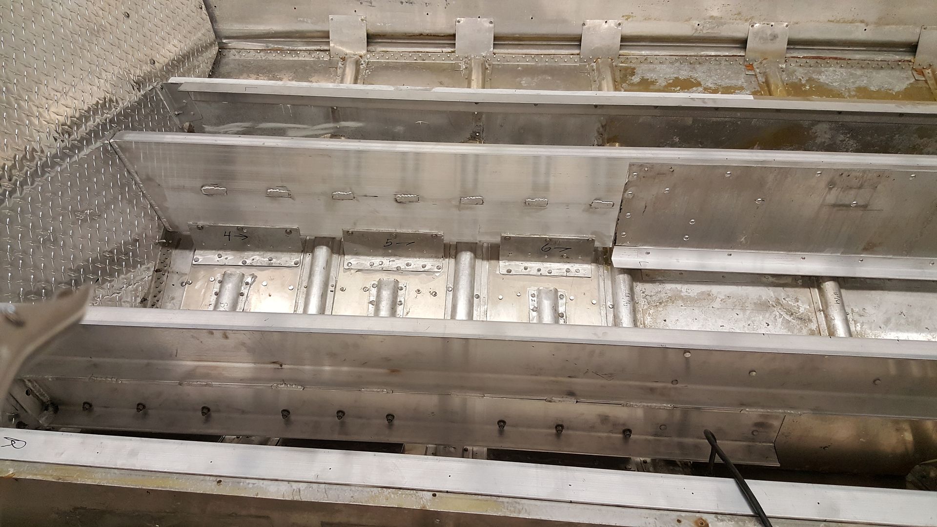
79 22' SS V5 Project

Mnsota

Seaman Apprentice
Joined
Sep 23, 2015
Messages
49
I sure do love these v5 hulls, in fact I have a crush on them. :lol:

My SeaNymph has a solid AL rub rail too in the harder alloy and that sucker is tough.

I do have to wonder though why not just replace the vinyl insert, easier and the cost would be less.

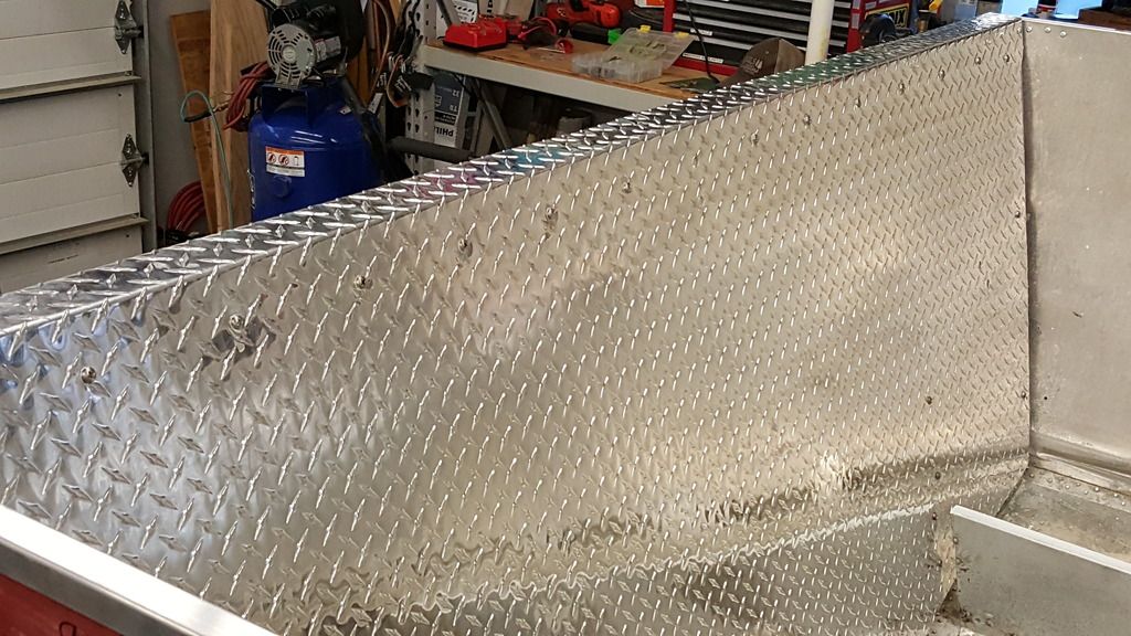
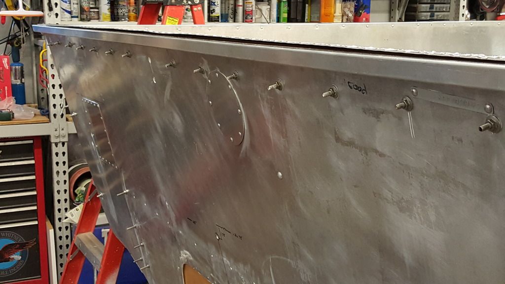
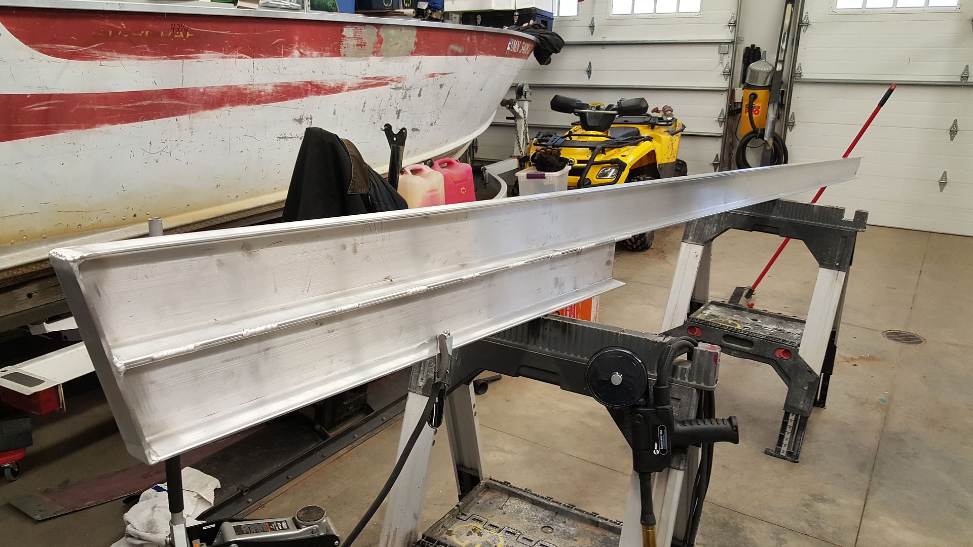
My old rails were so beat up it would have been much more work to get them to look decent. All in I have just under $100 in these new rails. $44 in alum. and about $50 for the structural pop rivits. The old rails had some pretty good gouges and bends in them. Id take a pic of how bad they were, but there outside and its -9 here and blowing like crazy. whats the harder alloy that yours are made of? these are 6061.
 

jbcurt00

Moderator
Staff member
Joined
Oct 25, 2011
Messages
24,863
How does the gunwale attach to the hull and new rubrail joint?

Your bow cap has been notched out?
 

Mnsota

Seaman Apprentice
Joined
Sep 23, 2015
Messages
49
Im going to make a new gunwale and either stich weld it to the rub rail or rivit it. The bow cap doesnt look modified. Maybe it was not the original.
 

jbcurt00

Moderator
Staff member
Joined
Oct 25, 2011
Messages
24,863
Maybe not original. Zooming in on the inside radius it looks cut as does the edges leading into the radius.

Only reason I mentioned it was that it might change how the gunwale fit.

If you blunt the bow joint in the new rubrail, about 3/4in it should leave a little joint between the port and starboard pieces you could weld or slip a backer into the joint and rivet the 2 pieces together AND allow the bow cap to fit better. Gap looks like its about 1/2in...
 

Mnsota

Seaman Apprentice
Joined
Sep 23, 2015
Messages
49
I see what your saying. Good idea on making the fit better. Thanks.
 

Mnsota

Seaman Apprentice
Joined
Sep 23, 2015
Messages
49
Got the transome in today. And no hernia, thats a heavy piece to lift over your head to get in boat for one person. I installed all the hardware above the floor backwards as the way you see it in the pic is how it will stay. Didnt want all the hardware to be sticking out for kids and tipsy adults to gouge them self with. I will cut the extra off the backside eventually.
 

Watermann

Starmada Splash of the Year 2014
Joined
Jan 12, 2013
Messages
13,753
Nice to have the heavy lifting done, looks nice. :thumb:

You can always use nut caps to cover the those cut off bolts. Do the v5's not have the side brackets that tie the side of the hull to the transom?
 

Mnsota

Seaman Apprentice
Joined
Sep 23, 2015
Messages
49
Good idea on the nut caps. Is that the same as a acorn nut? I guess i could put a acorn or nut cap on top of the nut currently in use. That would clean it up if i got the measurment to cut the bolt off just right.

No side brackets with this one. I would like to see a picture of how they were made at the factory if you have one. I have been planing on making two or three for each side, but dont have a good design yet. I would like to make it as strong as possible in case i do a engine swap with the other boat.
 

Mnsota

Seaman Apprentice
Joined
Sep 23, 2015
Messages
49
Is there a specific forum for people looking for parts or that have parts they are willing to part with?
 
Last edited:

jbcurt00

Moderator
Staff member
Joined
Oct 25, 2011
Messages
24,863

Mnsota

Seaman Apprentice
Joined
Sep 23, 2015
Messages
49
Thanks for the info. I need two of the 1/2" u bolts for the stern / bow. I have pretty much everything other than the hull that I wont be using.
 

Watermann

Starmada Splash of the Year 2014
Joined
Jan 12, 2013
Messages
13,753
No side brackets with this one. I would like to see a picture of how they were made at the factory if you have one. I have been planing on making two or three for each side, but dont have a good design yet. I would like to make it as strong as possible in case i do a engine swap with the other boat.

Here is what the side brackets look like on my Chief.

IMAG1302.jpg
 

GA_Boater

Honorary Moderator Emeritus
Joined
May 24, 2011
Messages
49,038
Acorn nuts would be a nice touch to finish off the transom bolts.

Early on you said you were adding some braces from the transom to the I/O motor mounts. I'm surprised only the motor and part of the jackplate fell off. That's a lot of weight being leveraged on the bracket with no added bracing. Got a brace plan yet?
 

Mnsota

Seaman Apprentice
Joined
Sep 23, 2015
Messages
49
Thanks for the pics watermann.

The jackplate broke. He told me the brand, but dont remember. He had several hundred hours on the set up before it broke. The bracing is what im going to work on next. Now that I got the transome in i can get better measurements. My plan Is to bend some 3/8" or 1/2" aluminum plate so it is against the transome directly inside the transome from the bracket. Then the the 90 deg. bend will come forward and bolt to some channel that will be fastened along the stringer. If I use 5" channel I can also bolt the channel to the engine mounts befor I rivet them down. Thats why I am moving the engine mounts so the outside edge is in line with the stringer. I also have the doublers ready to go under the engine mounts. I also have some 2.5 inch square alum tube that I plan to make a bracket to tie the transome to the side of the hull. Thats probably is hard to picture. But it should tie every thing together pretty well.
 

GA_Boater

Honorary Moderator Emeritus
Joined
May 24, 2011
Messages
49,038
With the motor on a bracket and all that weight on the end of the bracket, bracing is needed. We've seen what breaks on SC's with bad wood and splashwells from the weight. The bracket multiplies the forces.

It sounds like you have a good plan.
 

Mnsota

Seaman Apprentice
Joined
Sep 23, 2015
Messages
49
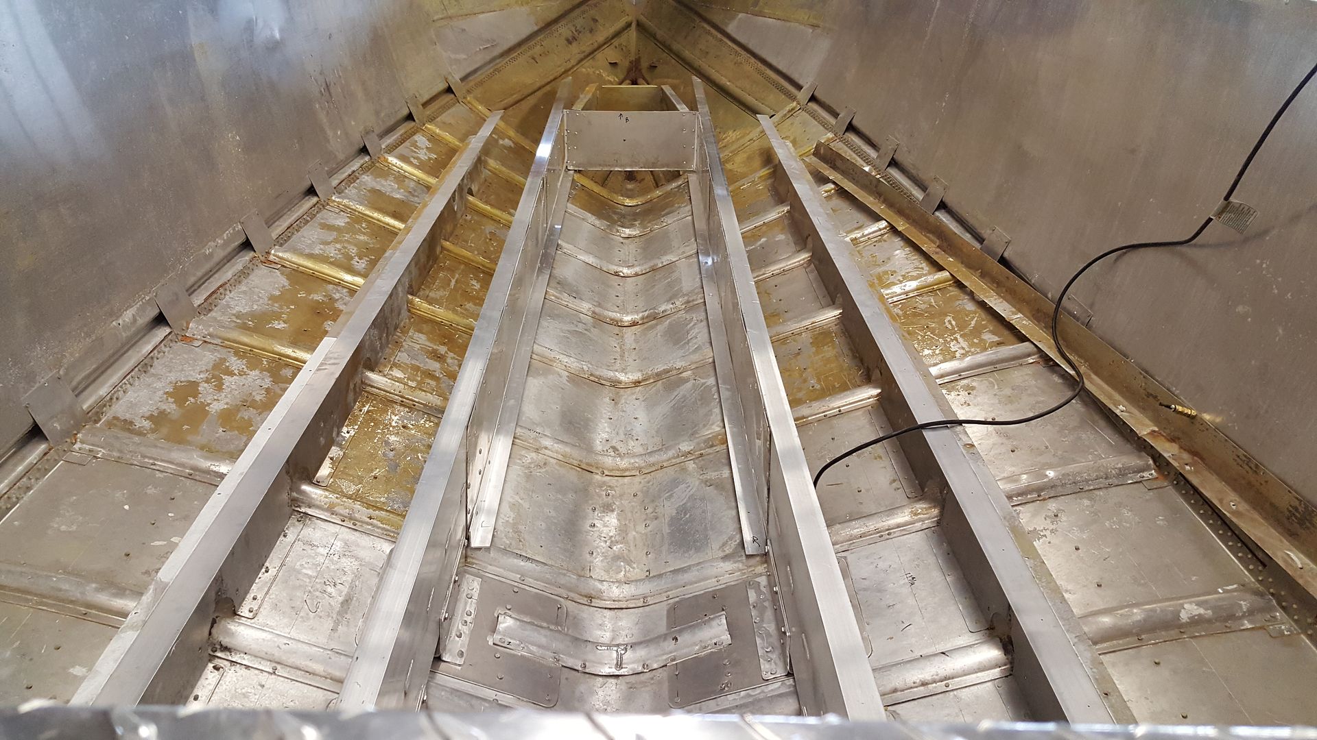
So after seeing everyone one here making such good progress on their builds, I thought I better get some thing done. So, Finally got some more work done on the v5 after getting side tracked with the what was supposed to be a quick wire and fuel line fix on our lund fishing boat. Anyway got the stringers reinforced to tie into transome and bracket. In the process of getting that done, I took the forward taper out of the center two stringer. That way I could slide the fuel tank forward to offset some of the weight of the motor being moved aft.
 

Mnsota

Seaman Apprentice
Joined
Sep 23, 2015
Messages
49
One thing thats requiring a lot of thinking is the center support for the fuel tank. Originally I was going to find a heavy pvc or alum pipe that had the same OD as the distance from the top of ribs to bottom of the sheet that will go under tank. That way the support would double as a support and a chase to get wire ect from bilge to front of boat. But the measurment goes from 4.25 on the back stringers to 5.75 on the very front one. Anyone got any ideas? I may still use a pipe with some spacers added to make up the difference. Or a composite 2 x 6 and taper it to fit correctly. Also still waiting on warm wx to finish stripping the inside of boat.
 

dozerII

Admiral
Joined
Oct 25, 2009
Messages
6,527
Some great progress right there, for the support for the fuel tank why not get a piece of aluminum bent in an inverted V with a couple of 1"flanges bent to rivet to the ribs.
 
Top