Electro-Mechanical Trim Indicators

tpenfield

Moderator
Staff member
Joined
Jul 18, 2011
Messages
17,689
I have been working on a project to replace the standard Mercruiser trim indicators with something that would be far more accurate. There are mechanical trim indicators available in the performance market, but those have some short comings in that they usually only monitor the lower end of the trim range and they take up extra space on the instrument cluster at the helm.

My previous boat had one of the mechanical indicators and it was pretty good for precisely setting the trim. My current boat has the standard type and it has been a nightmare knowing the trim (or tilt) of the outdrives. (twin engines)

So, I have been kicking around an idea of having a mechanical indicator that would work throughout the full trim & tilt range of the outdrive. Another forum member 'Mischief Managed' and I have discussed the idea over a couple of lunches during the past couple of years. I wanted to come up with a system that would use the trim cylinder's travel as a more true indication of the outdrive's position, and something that would also work with the existing gauge at the helm. . . since I have little extra space for another gauge/display.

Through several conceptual iterations, I have come up with a system that I plan on trying out on my boat this year to see if it will work for real. It is a combination of a mechanical trim indicator and an electrical indicator. The system has 3 main parts.

1) Trim Cylinder Actuator

2) Mechanical/Electrical Converter

3) Standard Trim Gauge Interface

Today, I finished a working system that I can install in the boat.

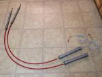
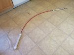
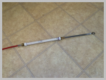
Here are parts #1 & #2 connected by a Morse C33 cable.
IMG_5852.jpg

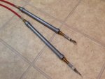
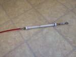
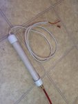
#1) The Actuator will mount to one of the trim cylinders on the outdrive and move the cable through its 8" of travel. Here it is fully collapsed (Full trim down)
IMG_5853.jpg

Here it is fully extended (Full Tilt up)
shapeimage_1.png

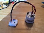
#2) The Converter is merely a large slide potentiometer that changes its resistance over the 8" of travel transferred to it by the cable. The electrical connections are the same as the standard trim sender unit, and essentially replaces it. This unit goes inside the engine compartment in the area of the transom.
IMG_5858.jpg


#3 ) The Interface unit at the helm connects to the existing gauge wiring at the helm and changes the resistance range of the 8" potentiometer to the range that the gauge expects to see. It is just a simple transistor circuit that I made, and also has a 'trim resistor' for adjusting the gauge reading.
IMG_5856.jpg

I was trying to make the Actuator (#1) and the Converter (#2) as a single unit, which would mean some of the electrical stuff would have to go under water. However, I felt that was going to be too challenging. So I went with a separate mechanical unit, which goes under water, and a converter which mounts inside the engine bay on the transom.

My testing of the system has demonstrated a very smooth and consistent gauge needle movement for the movement of the trim cylinder unit. So, I am looking forward to trying this out on the boat.

I still have a few more tweaks to make and I still need to make a second unit, since I have twin engines. My plan is to see how well they work and hold up in the marine environment, etc.

Just wanted to share my project and I will post updates as I install, test and use the system throughout the boating season.
 
Last edited:

Chris1956

Supreme Mariner
Joined
Mar 25, 2004
Messages
27,137
It will be interesting to see the utility of such a device. My theory is that since the loading of a boat is dynamic, the trimming needs to be dynamic as well. In your case, without your device, I would trim both motors up until speed is max, and then adjust trim (tabs if equipped) for side-to-side level. Measuring trim up would be by ear and feel of the boat handling.

Let us know if your system is better.
 

tpenfield

Moderator
Staff member
Joined
Jul 18, 2011
Messages
17,689
Yea, I have been trying to trim by feel, since the standard trim gauges don't really work that well. I find that you can trim by feel in flat water pretty well, but rough water not so much . . . which is most of the time.

That's why I liked the mechanical indicator that I had on my previous boat (Formula 242). Through experience you would learn the trim settings that matched the conditions and be able to 'dial it in' pretty quickly and then make any changes from there by feel. I'd go that route, except for the lack of space at the helm for the 'slide gauges'. Plus the mechanical gauges that you can buy are a bit pricey.

Another complication (I think) is the twin engines . . . I usually trim the boat side-to-side with the outdrives rather than the tabs. Generally, the boat rides fairly flat anyway, since it is a 10 foot beam, so not much lateral trim is ever needed. But, it is nice to have a starting point where the outdrives are both at the same position, which is nearly impossible with the standard trim gauges, at least from I have experienced.

This will be my third season with the 33 footer, and not having an accurate trim indicator was the most noticeable difference (to me), when graduating from the 24 footer that I had previously.

Hopefully, the utility will be there if all the technical stuff works out.
 

alldodge

Moderator
Staff member
Joined
Mar 8, 2009
Messages
40,705
Thanks for the heads up, look forward to seeing how it works out
 

tpenfield

Moderator
Staff member
Joined
Jul 18, 2011
Messages
17,689
Thanks for the heads up, look forward to seeing how it works out

Yea, I was not sure I would have the time to finish up the design for this season of boating, but I went through it this past week and figured a few things out that had been messing up the works.
 

tpenfield

Moderator
Staff member
Joined
Jul 18, 2011
Messages
17,689
UPDATE:

I finished the second mechanical trim sender unit. So, now it is a matter of waiting until I have the outdrives back on the boat, and then I can install the trim indicators.

Here are a few more pics . . .

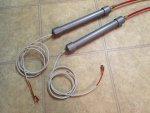
The 2 units . . .

IMG_5870.jpg

The mechanical actuators
IMG_5868.jpg

The electrical converters (slide Pots)
IMG_5869_2.jpg

The basic testing that I have done so far has been pretty good. Very smooth movement of my test trim gauge and good sensitivity to small movements of the trim cylinder. So, I am looking forward to seeing how these work out in the boat this season.
 
Last edited:

tpenfield

Moderator
Staff member
Joined
Jul 18, 2011
Messages
17,689
Looking good

Thanks, AD.

I did some 'final' testing of the system by hooking it up to a trim gauge and running the 'mechanical' part through the paces a bit. Here is a video (below) of the trim indicator device movement versus the gauge needle movement. This simulates what the gauge will read as the outdrive is raised & lowered.

Overall, I am pleased with the sensitivity of the 'system' in the trim range of the trim cylinders . . . which is only about 2-1/4" of the total 8" of extension by the trim cylinders.


Installation of this system should not be too bad . . . I have to drill a hole underneath the swim platform where it meets the transom . . . clamp the 'actuator' to the trim cylinder and fasten it to the end bolt . . . clamp the 'converter' piece inside the engine compartment (somewhere) . . . everything else is 'plug 'n play' with the existing wiring.

Before I can do all this, I still have to fix the bearing carrier issue that I have with the outdrives themselves (totally unrelated to this project though). :)
 

alldodge

Moderator
Staff member
Joined
Mar 8, 2009
Messages
40,705
By far that is far smoother then others I've seen. Look forward to seeing it in action. If there is a way after its installed maybe have the gauges next to the drives to compare. Might be a bit difficult to do.

Your carrier bearing my hole boat :facepalm: I'll trade ya projects :D
 

Bondo

Moderator
Staff member
Joined
Apr 17, 2002
Messages
70,506
Ayuh,..... That's very, Very Cool Ted,....

Looks like solid engineerin',..... ;)
 

tpenfield

Moderator
Staff member
Joined
Jul 18, 2011
Messages
17,689
By far that is far smoother then others I've seen. Look forward to seeing it in action. If there is a way after its installed maybe have the gauges next to the drives to compare. Might be a bit difficult to do.

Your carrier bearing my hole boat :facepalm: I'll trade ya projects :D

Yea, I had 'my turn' last year with the 'whole boat' thing. Not wishing that on anybody.
 

tpenfield

Moderator
Staff member
Joined
Jul 18, 2011
Messages
17,689
Ayuh,..... That's very, Very Cool Ted,....

Looks like solid engineerin',..... ;)

Thanks, Bondo . . . I got a trash can filled with the stuff that didn't work. I am anxious to see how it works for real.
 

tpenfield

Moderator
Staff member
Joined
Jul 18, 2011
Messages
17,689
Update:

I was planning on doing a test fitting and install the trim indicators this weekend . . . but . . . it looks like there is a wiring harness routed to where I was planning on mounting the potentiometer portion of the system. So, I am doing a bit of re-thinking and will probably take a run at it next weekend.

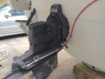
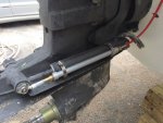
I did get a test fitting done . . . here are a could of pictures of the indicator temporarily mounted on the outdrive to test the fit and the cable run.
IMG_6110.jpg

IMG_6112.jpg

The total extension of the trim cylinders is 7-3/4 - 8", which is what I had designed to. So, they should work pretty well. I just need to figure out exactly how I want to mount the other end of this in the engine room / transom area.
 
Last edited:
tpenfield

Moderator
Staff member
Joined
Jul 18, 2011
Messages
17,689
Update:

I did the installation of my electro-mechanical indicators this weekend. Overall things went pretty good. I do need to mak a few tweaks to the electronics, but the system seems to be OK for now.

First thing was to drill 2 5/8" holes at a pretty shallow angle in the underside of the swim platform.
IMG_6151.jpg

Then I was able to feed the machanical cable (aka Morse 33C control cable) from the engine compartment through the holes that I drilled.
IMG_6152.jpg

Here are the cables pulled through the swim platform.
IMG_6154.jpg

Then it was a matter of assembling the actuators and strapping them to the trim cylinders
IMG_6157.jpg

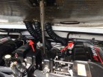
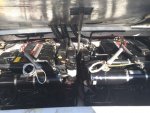
The electrical sensor portion goes anywhere it will fit inside the engine compartment. . . I had very little space to work with, but managed to strap the sensors to the main wiring harness. You can just barely see them where the arrows are pointing . . .
IMG_6162.jpg

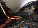
I then plugged the sensor wiring into the existing trim sender wiring . . . these sensors essentially replace the standard trim senders, so I was able to use the existing wiring, which saved a ton of time & hassle feeding new wiring.
IMG_6165.jpg

Continued on next post . . .
 
Last edited:
tpenfield

Moderator
Staff member
Joined
Jul 18, 2011
Messages
17,689
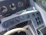
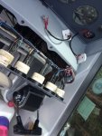
the next step was up at the helm where the interface modules connect to the existing trim gauges.
IMG_6166.jpg

Here is the gauge panel removed and the wiring exposed
IMG_6167.jpg

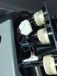
The modules are plug 'n play with the gauge connectors, as it has 'piggy back' connectors, so no wiring work is needed at the helm either. Here are the modules installed.
IMG_6169.jpg

Once the modules were connected, it was time for an initial test and adjustment of the system.

OMG . . . they work !!! :eek:


The only problem I had was that the trim limit stop had the gauges reading at 3/4 rather than 1/2 way (so in the red zone) I had planned on them stopping right at the edge of the green zone (1/2 way) and I could not adjust the interface units any more. So, I need to go back to the drawing board (so to speak) in the design of the gauge interface circuit. The nice thing, I re-engineer it a bit is that I can just make 2 more interface modules and replace these.

Operation is very smooth, repeatable and consistent between the 2 outdrives, based on my testing and measurements.

Here is a video of them in operation on the boat . . .


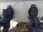
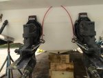
The sensitivty is great, as I had hoped, because the gauge moves about 3/4 of its travel within the entire trim range of the outdrive (which is only about 3" movement of the trim cylinders. The rest of the travel, which is the tilt/trailer range is the remaining 1/4 of the gauge reading. (about 5" of trim cylinder travel)

So, we will now see hoe these things do in real life ocean travel and how they hold up, etc.
 
Last edited:
tpenfield

Moderator
Staff member
Joined
Jul 18, 2011
Messages
17,689
One thing I noticed is that the gauges are 'dampened' a bit and therefore lag behind as the outdrive is moving up or down. Probably something I'll just get used to by making small movements during trimming and see where the gauge moves to . . .
 

tpenfield

Moderator
Staff member
Joined
Jul 18, 2011
Messages
17,689
Works a lot better then the Merc setup. Cu do's

Thanks, AD.

I did some testing and measuring to see how accurate (i.e. repeatable) they are and how close they are between the 2 engines. With the gauges at 1/2 . . . (needle in between the green and the red) the trim ram on the starboard engine was 21" (so extended 2") . . . After several up & downs of the outdrive and stopping back at 1/2 way on the gauge . . . the trim rams measured exactly 21" again.

The port outdrive was similarly repeatable, except the rams measured 21-1/4" at the gauge reading of 1/2 . . . so pretty close. I think I can tweak the adjustment a bit to get port & starboard exactly the same. Even small changes in the trim rams are reflected at the gauge. . . these types of movement would rarely show with the standard trim senders.

Anyway, I like the smooth operation, but the accuracy and sensitivity are the key benefits of this system. I'm anxious to get the boat in the water and test it out for real.
 
Last edited:
Top