Volvo Penta Trin Gauges inaccurate after refit 5.0 OSI

Status
Not open for further replies.

Steve Oest

Recruit
Joined
Feb 2, 2015
Messages
4
I have a 2007 Regal 3060 with twin 5.0 OSI engines. Bought it last year. The boat had XPD plastic drives which were coming apart and needed replacement. The trim gauges worked as designed and were accurate (note the trim gauges are Faria). This fall a local volvo dealer replaced the complete drives with new DPS A drives and transom plates the trim senders are new as well. While reviewing their work I tested the trim gauges.With keys on and the drives down the gauges read half up. I tried to adjust the senders and they are adjusted all the way down. I pulled one off and moved the pin and i cant get the gauge to show any lower than half down. While raising the drives the gauge begins to work when the drives are physically 1/3 up and then begin to work to show all the way up the rest of the cycle. both drives and gauges have the same fault I spoke to the dealer and they suggested I replace the gauges. I tried three types of gauges and all do the same thing ( wont read below half down). I tried in line resistors, didnt work, Faria stated I need the resistance measurement form the senders but the senders are three wire and I cant find any wiring diagrams to show what wires to use or what wires to measure from. Has anyone ran into this before? I am at a loss.
 

alldodge

Moderator
Staff member
Joined
Mar 8, 2009
Messages
40,741
I have a 2007 Regal 3060 with twin 5.0 OSI engines. Bought it last year. The boat had XPD plastic drives which were coming apart and needed replacement. The trim gauges worked as designed and were accurate (note the trim gauges are Faria). This fall a local volvo dealer replaced the complete drives with new DPS A drives and transom plates the trim senders are new as well. While reviewing their work I tested the trim gauges.With keys on and the drives down the gauges read half up. I tried to adjust the senders and they are adjusted all the way down. I pulled one off and moved the pin and i cant get the gauge to show any lower than half down. While raising the drives the gauge begins to work when the drives are physically 1/3 up and then begin to work to show all the way up the rest of the cycle. both drives and gauges have the same fault I spoke to the dealer and they suggested I replace the gauges. I tried three types of gauges and all do the same thing ( wont read below half down). I tried in line resistors, didnt work, Faria stated I need the resistance measurement form the senders but the senders are three wire and I cant find any wiring diagrams to show what wires to use or what wires to measure from. Has anyone ran into this before? I am at a loss.

As a non-VP expert I'll supply the following: It's my understanding that VP with the DP drives started using digital gauges which required digital senders. The 3-wire sender varies resistance between 100 ohms and 800 to 1100 ohms, and 700 ohms steady when rotated and measured on the outer wires. It could be that you have an analog gauge and now need a digital one. Below is the wiring diagram I found on one of DonS old links
VP DP trim wiring.jpg

Oh forgot sorry :welcome: to iboats
 
Last edited:

bruceb58

Supreme Mariner
Joined
Mar 5, 2006
Messages
30,476
Have you completely removed the trim sender(removed the 2 mounting screws and pulled off the sender) and rotated the shaft until the gauge shows all the way down?
 

Steve Oest

Recruit
Joined
Feb 2, 2015
Messages
4
Yes I completely removed the sender and rotated it. The lowest the sender will move the gauge is to the half way mark. I have seen this diagram before and it looks nothing like the system I have in the boat.
 

Fun Times

Moderator
Staff member
Joined
May 16, 2009
Messages
8,806
I tried to adjust the senders and they are adjusted all the way down. I pulled one off and moved the pin and i cant get the gauge to show any lower than half down.
Hi there, what pin did you move? Have a photo of your trim sender? if not, does it looks like this one? Volvo Penta New OEM Trim & Tilt Sender/Sensor 21484383 SX-A, DPS-A, DPS-B

While the info below is for an SX drive, it should get you where you want to be with your drive.

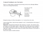
Here is some information from a manual on troubleshooting the trim sender and adjusting it.

Trim Sending Unit
Test Procedure

Remove sender from gimbal ring. Disconnect the sender 3-pin connector
inside the boat.
1. Attach an ohmmeter between the “A” terminal ribbed black lead and
the terminal “C” smooth black lead of the sending unit. Slowly rotate
the sending unit control nut counter clockwise until the ohmmeter is set
at infinity or open line (OL), then slowly rotate control nut counter clockwise
and ohmmeter will jump to 0 ohms. Continue to rotate control nut
for a highest ohmmeter reading of 600 ? 25 ohms.
2. Attach an ohmmeter between the “A” terminal ribbed black lead and
the terminal “B” white lead of the sender. Slowly rotate the sending unit
control nut counter clockwise until the ohmmeter is set at infinity or
open line (OL), then slowly rotate control nut counter clockwise and
ohmmeter will jump to a highest ohmmeter reading of 600 ? 25 ohms.
Continue to rotate control nut for a lowest ohm reading of 0 ohms.
3. Attach an ohmmeter between the “C” terminal smooth black lead
and the terminal “B” white lead of the sender. Slowly rotate control nut
counter clockwise. Ohmmeter should maintain a steady 600 ? 25 ohms.
If sender fails one of the three previous ohmmeter tests, replace the
sender.
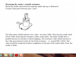
Adjustment Procedure
1 1. Attach an ohmmeter between the “A” terminal black lead and
the terminal “C” black lead of the sending unit amphanol connector A .
Slowly turn the sending unit control nut until the meter reads 11 ? 1
ohm.
2 2. With the pivot housing pushed in towards the gimbal housing,
install and engage the sending unit control nut into the pivot bolt head.
Install two trim sender mounting screws B finger tight.
3 3. With the pivot housing pushed in toward the gimbal housing,
check adjustment of sending unit. Rotate sending unit to obtain a 11 ?
1 ohm reading on the meter, then tighten mounting screws to a torque
of 18-24 in. lb. (2.0-2.7 N•m).

The sender is located on the starboard side of the gimbal ring.

attachment.php
 

alldodge

Moderator
Staff member
Joined
Mar 8, 2009
Messages
40,741
VP Trim sender test 1.png
VP Trim sender test 2.png


From pdf and note the wires change color depending on before or after week 19 of 1990
 
Last edited:

Steve Oest

Recruit
Joined
Feb 2, 2015
Messages
4
Thank you for all the advise I will try these next week when I get to the boat and report back. Again. Thanks again
 

Tonci.Rogoznica

Recruit
Joined
Jul 20, 2019
Messages
1
As a non-VP expert I'll supply the following: It's my understanding that VP with the DP drives started using digital gauges which required digital senders. The 3-wire sender varies resistance between 100 ohms and 800 to 1100 ohms, and 700 ohms steady when rotated and measured on the outer wires. It could be that you have an analog gauge and now need a digital one. Below is the wiring diagram I found on one of DonS old links


Oh forgot sorry :welcome: to iboats

Hi,

Can you please upload clearer wiring diagram? I just bought boat with the same Volvo trim system( and digital gauge) but previous owner cuts off the wires, bypass everything and used simply up and down switch.
 
Status
Not open for further replies.
Top