Hey Everyone,
I searched the forums but can't find anything to help me on this topic.
I just picked up a 1994 Chris Craft 268 Concept, and it has a 93/94 VP 7.4GL DPDM in it. When I bought it, it had new batteries, and I luckily discovered before being left dead in the water that the alternator isn't putting out any significant voltage (~4V at 3k RPM). I then noticed that the fusible link isn't connected to anything. It's hooked to the alternator, but there's no wire crimped to it and I found the cut wire that goes to the starter looking cleanly cut where it comes out of the engine harness by the alternator.
The boat does have a battery isolator, which appears to be added aftermarket, with a new wire (~10 awg) coming off the alternator, going to the isolator, and then splitting to 2 terminals that go inside the battery selector (I have a 2 battery setup). The battery selector is a 1/2/all/off, and it then has 3 large cables that go to each battery as well as to the starter.
I have 3 questions.
1.) Does it make sense that the fusible link is no longer part of the circuit with a battery isolator installed?
2.) Would a new alternator fix this problem, or do I need to dig deeper to see if there are any other wiring issues before replacing parts? (I started doing continuity checks and get high impedance continuity to frame through some of the alternator +leads - like the one hooked up to the choke stat on my carb)
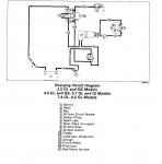
3.) Does anyone have access to information, or possibly the same setup in their boat, and would be willing to show me how things are supposed to be?
I have plenty more information if needed about the other components involved. Let me know if they will help.
Thanks!
I searched the forums but can't find anything to help me on this topic.
I just picked up a 1994 Chris Craft 268 Concept, and it has a 93/94 VP 7.4GL DPDM in it. When I bought it, it had new batteries, and I luckily discovered before being left dead in the water that the alternator isn't putting out any significant voltage (~4V at 3k RPM). I then noticed that the fusible link isn't connected to anything. It's hooked to the alternator, but there's no wire crimped to it and I found the cut wire that goes to the starter looking cleanly cut where it comes out of the engine harness by the alternator.
The boat does have a battery isolator, which appears to be added aftermarket, with a new wire (~10 awg) coming off the alternator, going to the isolator, and then splitting to 2 terminals that go inside the battery selector (I have a 2 battery setup). The battery selector is a 1/2/all/off, and it then has 3 large cables that go to each battery as well as to the starter.
I have 3 questions.
1.) Does it make sense that the fusible link is no longer part of the circuit with a battery isolator installed?
2.) Would a new alternator fix this problem, or do I need to dig deeper to see if there are any other wiring issues before replacing parts? (I started doing continuity checks and get high impedance continuity to frame through some of the alternator +leads - like the one hooked up to the choke stat on my carb)
3.) Does anyone have access to information, or possibly the same setup in their boat, and would be willing to show me how things are supposed to be?
I have plenty more information if needed about the other components involved. Let me know if they will help.
Thanks!