1978 80hp Mercury Power Trim Problems

surgemc

Cadet
Joined
Jan 21, 2013
Messages
27
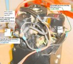
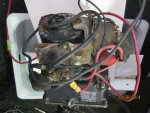
G'day everyone, we have a project boat going at the moment and are having a few problems with the power trim and tilt which was disconnected when we got it. The motor operates when we push the down button on the control box but nothing happens when we push either the up button or the trailer button. It has 3 wires coming from the control box which then go into a 2 pin plug. The wires appear to be blue, purple and green and the blue and green have been joined together before the plug.
My questions are:
1. Have the wires been joined correctly?
2. What tests can I do to trace the problem?
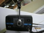
3. Does the position of the reverse lock knob have any affect on the operation?
Thanks in anticipation
Brett
 

surgemc

Cadet
Joined
Jan 21, 2013
Messages
27
These are pics of the pump and control box Solenoid  (640x480).jpg 2 Pin Plug (480x640).jpg Power Trim (480x640).jpg Contol Box  (640x480).jpg
 

Attachments

  • Solenoid  (640x480).jpg
    Solenoid (640x480).jpg
    181.4 KB · Views: 1

Chris1956

Supreme Mariner
Joined
Mar 25, 2004
Messages
27,148
Well, that is a bit different than I had thought, from my '77 Merc PTT unit, but I think I can help. You have a 2 solenoid PTT pump. Power is applied to the blue wire for up and the green wire for down. However, there is or was a trim limit switch on the starboard trim cylinder bracket. Those usually break, and when that happens, the up button on the throttle handle no longer works. To trim or tilt up, one must push the "trailer" button. However, since your trailer button doesn't work, something else is wrong.

First remove the two wire connector and see if there are really 3 female connections under it. The wiring should be power to the PTT buttons (red), power to the down solenoid from the trim down button(green) and power to the Up solenoid from both buttons (blue). However, Merc ran the power for the trim up button only from the PTT pump or the battery, thru the trim limit switch and then thru purple wire.
 

surgemc

Cadet
Joined
Jan 21, 2013
Messages
27
Chris 1956, thanks for your reply. The plug does have 3 female connections but as you can see one is damaged / burnt. I will try to clean it up and then connect all 3 wires separately. Can I assume the horizontal connection is for the purple wire? I have also attached 2 pics of what I believe must be the wires for the trim limit switch, but as you can see they are useless and I think they must have been bypassed. If so where would I look for the jumper lead and also does this then mean that the trailer switch on the control box will never work?
Thanks BrettTrim limit switch wires (2) (640x480).jpg 2-3 pin plug (640x480).jpg Trim limit switch wires (1) (640x480).jpg
 
Last edited:

Chris1956

Supreme Mariner
Joined
Mar 25, 2004
Messages
27,148
OK, If it were me, I would try to dig the burnt terminal out of the vertical slot. If you can do that, take new wires (about 12ga), in red, green and blue. Crimp and solder new male spade terminals on them and plug them into the three prong connector at the PTT pump. Run the three wires to the push button switch in the throttle handle. Connect the red to the common pole and blue to up and green to down, wrap the new wiring harness in that corrugated plastic wire wrap and call it a day.

If the female spade terminals in the PTT pump connector are too far gone, substitute ring connectors and connect the green and blue wires directly to their respective solenoids. Either solenoid can supply the +12VDC to power the PTT.

That will eliminate lot of issues. You can only use the throttle handle push buttons for trim and trailer, but I always thought that was most convenient.
 

surgemc

Cadet
Joined
Jan 21, 2013
Messages
27
I did some testing and re-wiring last night and it looks like I may have a faulty solenoid relay and possibly a faulty switch in the control box handle. I can get the pump to run by connecting the green wire directly to the large post on the solenoid but not the small connector it is meant to go to. This is why I'm assuming it's faulty.
I tried a continuity test on the wires to the switch but got no result. Is there a better way to that the switch is OK. .
 

surgemc

Cadet
Joined
Jan 21, 2013
Messages
27
I have now bought 2 new solenoids and replaced all the wiring on the pump. I have separated the Purple, Blue and green wires and run them directly to the solenoid. I can now get the pump to run down by pushing the down button on the throttle handle and up by pushing the Trailer button on the control box. The UP button still doesn't wor Trim limit switch wires (1) (640x480).jpg Trim limit switch wires (2) (640x480).jpg k. The wires shown in the pics are obviously the trim limit switch which is no longer connected. I have read on other posts here that when the limit switch is not working that stops the UP button from working however I haven't seen a solution to this anywhere. Ideally I don't want to attempt to replace the limit switch so can these wires be bypassed and if so how.
 

Chris1956

Supreme Mariner
Joined
Mar 25, 2004
Messages
27,148
OK, Put the wire you now have on your trailer up post on the trim up post. That solves your issue and bypasses the trim limit switch. You will no longer need to use the trailer switch.
 

Scaaty

Vice Admiral
Joined
May 31, 2004
Messages
5,180
No Title

Don't know if this helps or not, but the pump connections.
 

Attachments

  • photo208255.JPG
    photo208255.JPG
    56.1 KB · Views: 1

surgemc

Cadet
Joined
Jan 21, 2013
Messages
27
No Title

Thanks for the replies. I can get the motor to go up and down so i suppose that's all that matters. But I like to have things work the way their supposed to.Chris1956 when you talk about the Trim up post are you talking about at the pump or in the control box? I would really love to pull the control box apart to get a better understanding of the wiring at that end but can't for the life of me work out how to get it apart.
 

Attachments

  • photo207069.jpg
    photo207069.jpg
    146.1 KB · Views: 0

Chris1956

Supreme Mariner
Joined
Mar 25, 2004
Messages
27,148
When I said trim up post, I meant the connection for trim up, on the trim switch. Originally that motor has a three push button PTT panel. The lower button was trim or tilt down. The middle button was trim up, however, the trim limitswitch needed to be closed to have a trim function.. Pushing the middle and top buttons was tilt up. You new control has the same functions, but the buttons work independently, i.e. tilt up is one switch, tilt and trim down is another switch and trim up is the third switch.

It would appear that your trim limit switch is broken, as most are, of that vintage. The bad news is that you cannot have the original; trim function, with that broken switch. The good news is that you do not need it. I would wire the up wire (blue) to the trim up switch and call it a draw. Trim by feel, and don't worry about the trim limit switch function.
 

surgemc

Cadet
Joined
Jan 21, 2013
Messages
27
Thanks Chris1956, your help is much appreciated. Looks like I'll have to stay with using the Trailer button for tilt up and the control handle down button for down tilt and trim until I can work out how to pull the control box apart.
 

Chris1956

Supreme Mariner
Joined
Mar 25, 2004
Messages
27,148
Gee, Normally those control boxes have a couple of screws in the back holding them together.
 

surgemc

Cadet
Joined
Jan 21, 2013
Messages
27
Yes that's correct but there must also be something holding from the front as well. I have already cracked part of the casing trying to prise it apart. I'd say there must be a screw in the centre of the throttle handle under the button you push to keep it in neutral but due to it's age I'm reluctant to just keep pulling things off it with out being sure of the outcome.
 

Chris1956

Supreme Mariner
Joined
Mar 25, 2004
Messages
27,148
Sometimes those throttle buttons just pop off.

Also check the base of the throttle arm for an allen head screw. On my side mount control (completely different than your's, so just an example), the throttle arm must be in full reverse to expose the allen screw that allows the throttle handle to be removed.
 
Top