DVA Volt Reading Multimeters.-

Sea Rider

Supreme Mariner
Joined
Sep 20, 2008
Messages
12,345
If you don't count with a analog or digital multimeters with DVA reading capabilitie but count with one in which a DVA Adapter can be hooked to. Which side of the scale should the voltage selector be set, AC or DC setting ? Plan to acquire a Electronic Specialties DVA Adapter soon to read Exciter, Ignition Coils and CDI units.

Happy Boating
 

QBhoy

Fleet Admiral
Joined
Mar 10, 2016
Messages
8,308
Unless I have this wrong (after a works Xmas night out), I think you may need to switch between DC and AC, depending on the application and what stage of the electrical circuitry you are at. On Stator charged 2 strokes, AC is turned to DC at the rectifier, last time I was in and about these engines.
Hopefully I?ve made sense and not missed the point !
 

GA_Boater

Honorary Moderator Emeritus
Joined
May 24, 2011
Messages
49,038
Last edited:

Sea Rider

Supreme Mariner
Joined
Sep 20, 2008
Messages
12,345
Thanks, will have an interesting read out along a nice coffee, the issue is that a meter with DVA reading capability costs 30 to 50% more money than a good digital meter along a spare DVA adapter. A friend of mine uses the latter to work on motorcycles and the readings are quite steady. It's a tool to have at hand for precise and fast electrical troubleshooting.

Happy Boating
 

82rude

Rear Admiral
Joined
May 8, 2012
Messages
4,082
Search the net I'm sure I read an article that somebody referenced a formula where you don't need to have dva.An elect I'm not nore have I ever slept at a holiday inn lately,lol.I could be totally off base here but i vaguely remember searching dva meters when I came across the article.
 

Sea Rider

Supreme Mariner
Joined
Sep 20, 2008
Messages
12,345
Searched the Net for a while, foud an Aussie that has a elctronic diagram of just 4 peanuts cost components to build a nice DVA adapter for digital multimeters. Converts AC outputs into DC read outs. Will check parts along assembling costs. Why pay out of this world prices if you can built one at a fraction of the retailers $ 30-40 asking price for an eye catching one. Ain't the Net fabulous!!

Happy Boating
 

GA_Boater

Honorary Moderator Emeritus
Joined
May 24, 2011
Messages
49,038
If you had said the Electronic Specialties adapter was too expensive, I could have shown dozens of plans plus all the ones here in the forums. :D

About 10-15 USD to build your own before Radio Shack bellied up.
 

Sea Rider

Supreme Mariner
Joined
Sep 20, 2008
Messages
12,345
If you had said the Electronic Specialties adapter was too expensive, I could have shown dozens of plans plus all the ones here in the forums. :D

About 10-15 USD to build your own before Radio Shack bellied up.

If you happen to have a DVA diagram post it would love to have a look. Thursday will have a close cost about builing one for mysel. Was about to bite the bullet and go for a ES DVA meter, but now knowing what's inside and the parts cost no way, with the savings prefer to buy a flywheel puller instead.

Happy Boating
 

sam am I

Commander
Joined
Jun 26, 2013
Messages
2,169
http://forums.iboats.com/filedata/fetch?id=6957324 or click here

Enter the following w/o quotes in your fav search engine where "dva circuit" are your key search words and "forums.iboats.com" is where you want to go search for those key words.......

"dva circuit site:forums.iboats.com" or click here

If ya have the extra scratch, you might want to skip the whole "dva" hype and consider just picking up a nice meter that has the "peak hold" function. That is all this circuit is (a discrete peak hold) and many meters have it already built in and for many years now. All the meters that I'm aware of and have used or own are plenty fast and more than adequate to capture any of the circuit speeds (rise time) that are present in past and present engines. Here is the one is use just as an example. This manu of meter makes meters that'll last you a life time and probably will be the last you'll need.
 
Last edited:

Sea Rider

Supreme Mariner
Joined
Sep 20, 2008
Messages
12,345
Thanks Sam Am I , seems that schematic diagram is very popular worldwide, it's same found on the Net, the difference is that the latter is missing important information such as polarity at both sides which is a must know. Fluke high quality meters just to read DVA volts now and then will be too pricey.

Happy Boating
 

sam am I

Commander
Joined
Jun 26, 2013
Messages
2,169
missing important information such as polarity at both sides which is a must know.

Depends if the cap is a polarized cap or not. The industry standard is when the polarity is omitted, it is a non-polarized cap being used, which btw, a non-polarized cap could certainly be used here.

Fluke high quality meters just to read DVA volts now and then will be too pricey.

Definitely, if that is all you would use it for......I use mine for all its features, call me crazy
 
Last edited:

GA_Boater

Honorary Moderator Emeritus
Joined
May 24, 2011
Messages
49,038
One thing in the diagram is the capacitor 2.2 uF, not 22 uF as noted in this thread - http://forums.iboats.com/forum/engi...0403-how-to-make-a-dva-adapter-for-multimeter

The polarity markings on the capacitor are a line, "-" sign or the shortest lead are connected to the bottom.

re136.jpg


The diode marking is a line around the diode is the end connected to the long lead of the capacitor.

do41.jpg


Resistor makes no difference which end because resistors aren't polarity sensitive.

Resistor_FIX.jpg


Put it all together and

ecomp.PNG
 

Sea Rider

Supreme Mariner
Joined
Sep 20, 2008
Messages
12,345
Thanks really appreciated, on this near same DVA diagram there's a 300 Ohm resistance between D1 and C1


Mod DVA Adapter.JPG


Not counting with this extra R1 resistance be an issue, say readings not being that accurate, whatever ?

Happy Boating
 
Last edited:

sam am I

Commander
Joined
Jun 26, 2013
Messages
2,169
Not counting with this extra R1 resistance be an issue, say readings not being that accurate, whatever ?

I'm not sure I can follow your question fully but, I think you're asking if the extra resistance (300 ohms) that R1 adds to the circuit will have any effect on the readings accuracy?

If so, no!

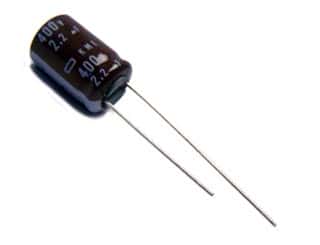
It'll just change the charge rate (time to fully charge the cap) of the cap ever so slightly, not even enough to notice........t=RC ( 300 * 2.2e-6 = 0.00066 s) and 5t = full charge = (5 * 0.00066 s = 0.0033 s)

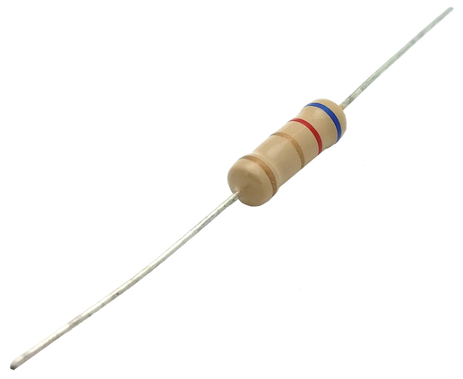
I believe the designer added R1 (300 ohm series resistor) to limit current. Either to protect the diode and/or the device/s (boats electronics) being measured in the event of a mishaps. e.g. your dva fixture has its output leads short circuited (leads touch or slip to ground, etc). or even if the dva's cap shorts out at some point in its life time.......If any of those examples happen, there is a chance the diode and/or the electronics being tested could be smoked and as stated, the 300 ohms R1 would help prevent this by limiting the current.

There is also the case of R1 limiting the inrush current when a fully discharged cap causes a pretty big current spike through the diode upon intial measurements BUT, its so fast, the diode will be fine.....Moot point there according to the data sheet on a 1N4004

I think if it were me, and I had to use something like this and I wanted to protect the diode AND the DUT (device/s under test) while using this thing inline with my meter, I'd use a fuse in place of R1 (or on anode side of D1) due to the fact R1 will just burn up upon protecting the boat/diode. This is fine, that is if it's flame proof fusiable resistor, otherwise.......

A 1 Amp fast blow for example fuse would be simple and a better method IMO. So, as stated above, if your dva circuit short (cap shorts etc) and/or you inadvertently cross leads or touch one to ground, whatever, the fuse will open quite fast (faster than a opening/buring up carbon or metal oxide resistor or even fusible resistor), thus protecting from potentially damaging your boats electronics ig or CDI or whatever it is your testing.

I'd still however recommend (I'll admit though, I guess ;) I like building this stuff too) ya consider a meter that is made to do this job, the fluke I referred to was just an example, there are plenty of meters out there that preform this function....another example is here
 
Last edited:

Sea Rider

Supreme Mariner
Joined
Sep 20, 2008
Messages
12,345
Thanks again for the excellent explanation and time involved, so to count or not with extra 300 Ohm resistor will not make a difference. Good idea installing a 1 amp fuse instead of a resistor.

Will be fun making a DV Aapter to troubleshoot outboards CDI modules which will need to be measured while crancking the OB. All other electrical components can be measured checking its individual resistance comparing them to their factory specs which I know, but a DV Adapter will confirm if electrically altered or already shot dead when crancking OB.

Happy Boating
 
Last edited:

Sea Rider

Supreme Mariner
Joined
Sep 20, 2008
Messages
12,345
Got the 6 parts needed for this DVA DIY proyect for just $ 4.30 peanuts cost.

DSCF7298.JPG

When components are finally welded onto small board will probably hide it inside a AA battery plastic case, that way can open it up if any components needs to be changed.


Happy Boating
 

GA_Boater

Honorary Moderator Emeritus
Joined
May 24, 2011
Messages
49,038
Got the 6 parts needed for this DVA DIY proyect for just $ 4.30 peanuts cost.


When components are finally welded onto small board will probably hide it inside a AA battery plastic case, that way can open it up if any components needs to be changed.


Happy Boating

OH NO - Assembly required AND batteries NOT included! :lol:
 

Sea Rider

Supreme Mariner
Joined
Sep 20, 2008
Messages
12,345
I'm about to finish my DIY DVA adapter project. Is it OK to remove spark plugs as to have the least cylinder compression while cranking the engine to check DVA outputs ? Assume you must not disconnect Exciter Coil, CD unit to be DVA measured individually.

Some say could fry component by doing so as there is too much electric load going on, so testing with multimeter's test leads while each one remains hoocked to each other is the way to go while cranking OB, right ?

Happy Boating
 
Last edited:

jbuote

Lieutenant Junior Grade
Joined
Aug 17, 2016
Messages
1,001
Still a newbie really, but pretty sure you can... Just ground the spark plug leads without the spark plugs.. Use a jumper of sorts to ground them.. that way the circuit is complete and doesn't overload anything right?
 

Sea Rider

Supreme Mariner
Joined
Sep 20, 2008
Messages
12,345
Still a newbie really, but pretty sure you can... Just ground the spark plug leads without the spark plugs.. Use a jumper of sorts to ground them.. that way the circuit is complete and doesn't overload anything right?

Probably not a good idea to ground plug lead with spark plug removed, that's a direct shortage to ground. Assume it's a different story shorting a removed plug to ground to check spark than shorting the lead direct to ground. CD's are very expensive to mess with them.

When testing cylinder compresion with removed plugs to ease cranking OB, nothing happens to electrical components, you need min 4-5 cranks per cylinder to start building pressure on tester to achieve an accurate reading compare to just 1 strong crank per electrical component to fully read its DVA output.


Happy Boating
 
Last edited:
Top