achris
More fish than mountain goat
- Joined
- May 19, 2004
- Messages
- 27,468
Mercruiser Thunderbolt ignition systems.
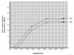
Mercruiser introduced the Thunderbolt IV onto their engines in 1982, alongside the introduction of the 1-R drives. The TB-IV system was used until the introduction of TB-V mid-way through 1996. Thunderbolt V was an improvement on an already exceptionally reliable and well performing system. TB-IV modules were programmed with each specific engine's own timing curve.
The modules started out as a large box mounted to the (usually) Port exhaust elbow.
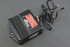
Later the module housing was redesign. It became considerably smaller and was mounted to a plate that fitted into the place of the first generation modules. The flying leads became a socket for a plug and the interconnect wires became part of the engine harness.
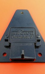
This module was later removed from the plate and mounted directly to the outside of the distributor body with a suitable heat transfer compound.
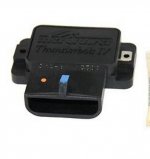
All the different modules do the same job. They are supplied by a 12 volt wire, usually purple, via the positive terminal of the coil. They supply a current controlled 12 volts for the sensor (located inside the distributor) and receive a series of 5 volt pulses back from the sensor. More on the sensor later. When a negative going pulse (one going from 5 volts to ground) is received the module electronics calculates the time required to fire a spark, based on the engine speed and whether it's a 6 cylinder or 8, and the timing curve programmed into the module. The coil is then fired via the grey wire on the coil negative terminal, just like a points based system. The coil negative terminal also carries another grey wire, this for the signal for the dash tachometer. The coil, on all engines, be they TB-IV or TB-V is 0.6Ω to 0.8Ω primary resistance and 9.4kΩ to 11.7kΩ secondary.
The distributor internal sensor.
All engines use the same distributor sensor, V6, V8, small block, big block. 2 versions were released. The first had just 2 screw terminals that sat on the outside of the distributor. One terminal was for the white/red wire from the module and the other for the white/green wire from the module. On engines designed for the 1- and Alpha series drives, another white/green wire went from the sensor terminal to the shift interrupt switch. This sensor design relies on one of the mounting screws for its ground.
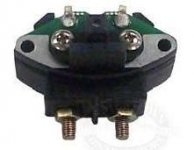
The sensor was later redesigned to remove the screw terminals and incorporate 'flying leads', and include a black ground wire. It also encapsulated the solder connections and the circuit board, making it more durable and less subject to corrosion.
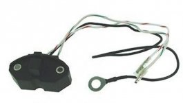
The original screw terminal sensor was made NLA, and a new sensor kit includes a set of adapter leads to allow easy installation and connection of the new sensor assembly.
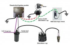
Below is a diagram showing how the various parts of the system connect together. (BTW. The shift interrupt works by grounding the output pulses from the sensor in the distributor. No pulses, no sparks.)
THUNDERBOLT V
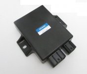
TB-V introduced a 'variable' advance curve. The actual engine timing is based on a pre-programmed curve (much like the TB-IV curve), but the electronics is able to modify the curve based on engine speed, rate of change of engine speed (ie, if the engine is accelerating) and if fitted, a knock sensor output. The basis of the system remains the same as the TB-IV, and uses the same distributor sensor for the trigger pulses. The module also came in a new package. In addition to the programming, TB-V can also have a knock sensor connected, which also modifies the timing curve, and an extra wire to force the unit into 'base mode' for setting of the initial timing, and a feed from an overheat sensor and a connection to the audio alarm system. As TB-IV is now also NLA, this new module is the direct replacement for any TB-IV modules that fail, again based on each specific engine and its advance curve. Ordering a TB-V module as a replacement for a failed TB-IV will include any connectors that need to be changed too.
Fault-finding.
Now we know how the system is connected and what each part does, fault-finding becomes quite simple.
And as the only differences between TB-IV and TB-V are the program, a possible knock sensor and an extra wire (base mode), troubleshooting uses the same procedure and flowchart for both systems.
For troubleshooting I always remove the tacho feed wire and the white/green to the shift interrupt switch, eliminating them as a possible cause of a problem. I also remove the HT lead from the centre post of the distributor cap and put a spark plug into it, lay it on the engine where it is well grounded and I can see it. A good spark if a health blue one that you can hear go 'crack'. A yellow spark is weak and may not fire a fuel charge properly.
The most obvious checks are, has the system got 12 volts? Are all components properly grounded? Are all the wires intact?
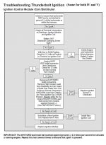
Once we can answer YES to those questions we can move onto the next step, running through the troubleshooting flowchart. This chart has been published many times on these forums, but I have included it here anyway.
The steps need to be followed in order and without missing a step.
And remember, if the results are strange, or intermittent, start looking for bad grounds or dodgy wires.
Mercruiser introduced the Thunderbolt IV onto their engines in 1982, alongside the introduction of the 1-R drives. The TB-IV system was used until the introduction of TB-V mid-way through 1996. Thunderbolt V was an improvement on an already exceptionally reliable and well performing system. TB-IV modules were programmed with each specific engine's own timing curve.
The modules started out as a large box mounted to the (usually) Port exhaust elbow.

Later the module housing was redesign. It became considerably smaller and was mounted to a plate that fitted into the place of the first generation modules. The flying leads became a socket for a plug and the interconnect wires became part of the engine harness.

This module was later removed from the plate and mounted directly to the outside of the distributor body with a suitable heat transfer compound.

All the different modules do the same job. They are supplied by a 12 volt wire, usually purple, via the positive terminal of the coil. They supply a current controlled 12 volts for the sensor (located inside the distributor) and receive a series of 5 volt pulses back from the sensor. More on the sensor later. When a negative going pulse (one going from 5 volts to ground) is received the module electronics calculates the time required to fire a spark, based on the engine speed and whether it's a 6 cylinder or 8, and the timing curve programmed into the module. The coil is then fired via the grey wire on the coil negative terminal, just like a points based system. The coil negative terminal also carries another grey wire, this for the signal for the dash tachometer. The coil, on all engines, be they TB-IV or TB-V is 0.6Ω to 0.8Ω primary resistance and 9.4kΩ to 11.7kΩ secondary.
The distributor internal sensor.
All engines use the same distributor sensor, V6, V8, small block, big block. 2 versions were released. The first had just 2 screw terminals that sat on the outside of the distributor. One terminal was for the white/red wire from the module and the other for the white/green wire from the module. On engines designed for the 1- and Alpha series drives, another white/green wire went from the sensor terminal to the shift interrupt switch. This sensor design relies on one of the mounting screws for its ground.

The sensor was later redesigned to remove the screw terminals and incorporate 'flying leads', and include a black ground wire. It also encapsulated the solder connections and the circuit board, making it more durable and less subject to corrosion.

The original screw terminal sensor was made NLA, and a new sensor kit includes a set of adapter leads to allow easy installation and connection of the new sensor assembly.
Below is a diagram showing how the various parts of the system connect together. (BTW. The shift interrupt works by grounding the output pulses from the sensor in the distributor. No pulses, no sparks.)

THUNDERBOLT V
TB-V introduced a 'variable' advance curve. The actual engine timing is based on a pre-programmed curve (much like the TB-IV curve), but the electronics is able to modify the curve based on engine speed, rate of change of engine speed (ie, if the engine is accelerating) and if fitted, a knock sensor output. The basis of the system remains the same as the TB-IV, and uses the same distributor sensor for the trigger pulses. The module also came in a new package. In addition to the programming, TB-V can also have a knock sensor connected, which also modifies the timing curve, and an extra wire to force the unit into 'base mode' for setting of the initial timing, and a feed from an overheat sensor and a connection to the audio alarm system. As TB-IV is now also NLA, this new module is the direct replacement for any TB-IV modules that fail, again based on each specific engine and its advance curve. Ordering a TB-V module as a replacement for a failed TB-IV will include any connectors that need to be changed too.

Fault-finding.
Now we know how the system is connected and what each part does, fault-finding becomes quite simple.
And as the only differences between TB-IV and TB-V are the program, a possible knock sensor and an extra wire (base mode), troubleshooting uses the same procedure and flowchart for both systems.

For troubleshooting I always remove the tacho feed wire and the white/green to the shift interrupt switch, eliminating them as a possible cause of a problem. I also remove the HT lead from the centre post of the distributor cap and put a spark plug into it, lay it on the engine where it is well grounded and I can see it. A good spark if a health blue one that you can hear go 'crack'. A yellow spark is weak and may not fire a fuel charge properly.
The most obvious checks are, has the system got 12 volts? Are all components properly grounded? Are all the wires intact?
Once we can answer YES to those questions we can move onto the next step, running through the troubleshooting flowchart. This chart has been published many times on these forums, but I have included it here anyway.
The steps need to be followed in order and without missing a step.
And remember, if the results are strange, or intermittent, start looking for bad grounds or dodgy wires.
Last edited:


