Part Identification

rotorhead22

Seaman
Joined
May 19, 2015
Messages
74
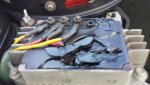
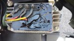
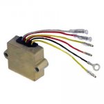
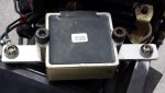
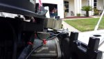
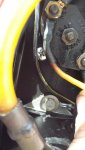
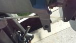
Good morning to all, I am new to boating and needed to seek a good source of info and found this forum which appears to be a great source. I tried using the search option for this issue, but nothing came up. I have a 1989 Sea Ray 16' Bowrider with a 100 Mercury outboard engine. We have had this boat in the gulf and have had no issues. When we went to a nearby lake, a wire broke loose from a poor crimp connecter installation (under the transom in a cubby hole) and the attached pictures are of a component that got so hot the rubber material was smoking pretty good. I disconnected the battery immediately and let things cool down. This component is on top of the engine, forward of the flywheel toward the transom. I was able to troubleshoot this issue and stripped the wires more or less by feel and twisted them together. the more cranked just fine three more times with no issues.The parts diagrams that I find state that this component is a "kit". I ordered what I thought was this component but instead received a voltage regulator which is just fine because I'm sure that this will eventually fail also. So after this long winded tale, what is he actual name of this component? T


Texasmark

Supreme Mariner
Joined
Dec 20, 2005
Messages
14,557
Your pictures didn't copy. What color is the wire and what diameter is it, that came loose? 100 hp '89 is said to be a 4 cyl looper. If so, go to the side of your starter and follow the large red wire to a component which is the starting solenoid (high current switch) and the input terminal (on the other side of it) is usually a junction connection for 12v distribution. Considering all the wires connected there, how large is it?
 

rotorhead22

Seaman
Joined
May 19, 2015
Messages
74
Your pictures didn't copy. What color is the wire and what diameter is it, that came loose? 100 hp '89 is said to be a 4 cyl looper. If so, go to the side of your starter and follow the large red wire to a component which is the starting solenoid (high current switch) and the input terminal (on the other side of it) is usually a junction connection for 12v distribution. Considering all the wires connected there, how large is it?

Can you see the pictures now?
 

rotorhead22

Seaman
Joined
May 19, 2015
Messages
74
No Title

Hopefully this will work better. The tach does not work .
 

Attachments

  • photo221441.jpg
    photo221441.jpg
    81.5 KB · Views: 0
  • photo221442.jpg
    photo221442.jpg
    91.1 KB · Views: 0

Texasmark

Supreme Mariner
Joined
Dec 20, 2005
Messages
14,557
Seems pretty straight forward. The two ac inputs from the stator, the yellow wires, are there, the ground, black wire, is under the case mounting screw in the lower left, the red output wire of the rectifier/regulator if it contains one, and a hole where a terminal belongs. Going to bet if a stud occupied this hole it would have a grey wire attached to it that went to your tach sense input. Seems reasonable that your tach doesn't work.

If you want it to work purchase (on this site for one) a regulator/rectifier with the tach signal. Find the grey wire in your wiring harness in the engine and connect it. The grey wire comes through the engine to remote control wiring harness connectors in the engine.
 

rotorhead22

Seaman
Joined
May 19, 2015
Messages
74
No Title

Thank you for the assistance it is greatly appreciated. The newly attached photo is what I received for the burnt model I was asking about. Do you have any recommendations for a service manual for this engine (100 hp '89 is said to be a 4 cyl looper)?
 

Attachments

  • photo221518.jpg
    photo221518.jpg
    16.5 KB · Views: 0

Texasmark

Supreme Mariner
Joined
Dec 20, 2005
Messages
14,557
Thank you for the assistance it is greatly appreciated. The newly attached photo is what I received for the burnt model I was asking about. Do you have any recommendations for a service manual for this engine (100 hp '89 is said to be a 4 cyl looper)?

Looks like you have all the necessary wires. Ensure the black ties to the engine block or if to the mounting plate, that the plate is securely grounded to the block where the battery - wire is connected. The reds probably will both go to the input terminal (junction point for 12v supply) on the starter solenoid. The grey tach wire is in your wiring harness somewhere. On 7 pin connectors it's not in the connector but on a wire tie wrapped to the wiring bundle, near the connector, along with the tan wires used for temp and oil warnings. On the other end of the cable, at the control, they will be loose also since you need to have access for the tach connection and separate warning device.....some boats have a light on the instrument panel that lights if you have a failure...secondary warning device for situations where there is so much background noise you can't hear the audible alarm that is part of or adjacent to (in the harness) the control.

Seloc is sold on here and I have downloaded and used their manual. You should have no problem in finding one for that engine. For what it's worth Merc has numerous wiring options, even in one year of manufacturing so a later model manual, if you can't find one that far back.....first year of production for the 100 4 cyl, should have a diagram that matches yours. My manual was a '96 print and was useful on my 2002 90.
 

rotorhead22

Seaman
Joined
May 19, 2015
Messages
74
No Title

Had to fabricate a bracket from aluminum stock, but I think that it should stay cooler.The was a ground wire on the old regulator which traced down to a screw in the block that was loose. It appears that this part was replaced before and was not secured very well.
 

Attachments

  • photo221945.jpg
    photo221945.jpg
    151.4 KB · Views: 0
  • photo221946.jpg
    photo221946.jpg
    190.6 KB · Views: 0
Last edited:

rotorhead22

Seaman
Joined
May 19, 2015
Messages
74
No Title

Tach still does not work after connection to new part. I suspect the trouble is behind the tach itself. I will remove gauge cluster and inspect
 

Attachments

  • photo221947.jpg
    photo221947.jpg
    153.3 KB · Views: 0
  • photo221948.jpg
    photo221948.jpg
    76.5 KB · Views: 0

LundTamer

Cadet
Joined
May 13, 2015
Messages
22
does anyone know if it matters which yellow wire is connected to witch yellow wire since both the bullets are male on one side and both female on the other I don't know if it matters which stator output goes to which and the manual doesn't specify either.... given they didn't reverse the gender on one of them like they did the two red wires I'm thinking it doesn't matter but appreciate any insight...
 

Texasmark

Supreme Mariner
Joined
Dec 20, 2005
Messages
14,557
does anyone know if it matters which yellow wire is connected to witch yellow wire since both the bullets are male on one side and both female on the other I don't know if it matters which stator output goes to which and the manual doesn't specify either.... given they didn't reverse the gender on one of them like they did the two red wires I'm thinking it doesn't matter but appreciate any insight...

Doesn't matter, isolated AC circuit. Your rectifier will pick one and ground it probably in a full wave bridge configuration (4 diodes) which yields the highest output voltage from a 2 wire input. Red wires it does matter as I said, the rectifier has established ground and the reds need to stay hot.
 

rotorhead22

Seaman
Joined
May 19, 2015
Messages
74
I have attached the only reference I could find and wired it this way. Sucks that these parts dont come with wire diagrams.
 

Attachments

  • 194-5279.pdf
    29.2 KB · Views: 0

Texasmark

Supreme Mariner
Joined
Dec 20, 2005
Messages
14,557
I have attached the only reference I could find and wired it this way. Sucks that these parts dont come with wire diagrams.
Any questions about the CDI instructions?

One thing I noticed and they mentioned (heat sinking), was your bracket for mounting your rectifier is not very large and as such is not really a heat sink like if it were mounted to a heat sink (with thermal conducting white paste) like my last one was to which they elude, to a large plate (aluminum I'd suppose which as you know is a super heat conductor), which also contained numerous components and was itself electrically connected to the engine block where the battery - terminal was also connected.
Their conduction test is a bit much for a shade tree do-it-yourselfer, but you can "improvise, adapt, overcome" (unofficial USMC motto), compliments Clint Eastwood in the Granada invasion movie. If in doubt the next time you think you are having to do a lot of battery recharging/maintaining, just put your finger on the case of the module. If you can hold your finger on it and not have to take it off (because it'll burn you) then you are good to go where you are. 70 degrees centigrade is where you have to take your finger off and diodes are good to 85 for commercial grade and over 100 for military.

On ground you have two types, one with a black ground wire and one discussed in the CDI instructions as internally completed and the case is used as the connecting point to get back to the battery -.

The resistance checks they mention prove that it is a full wave bridge rectifier (4 diodes) preceding the regulator part. If you want to know what that is and how it's wired, google it. Just remember that you have a preset regulator behind it before you get to the case ground and red wire 12v output. The grey tach wire counts the ac peaks probably at the output of the FW bridge rectifier.

Hope I didn't confuse you. If so, or like I said the CDI instructions did, ask!
 

rotorhead22

Seaman
Joined
May 19, 2015
Messages
74
Any questions about the CDI instructions?

One thing I noticed and they mentioned (heat sinking), was your bracket for mounting your rectifier is not very large and as such is not really a heat sink like if it were mounted to a heat sink (with thermal conducting white paste) like my last one was to which they elude, to a large plate (aluminum I'd suppose which as you know is a super heat conductor), which also contained numerous components and was itself electrically connected to the engine block where the battery - terminal was also connected.
Their conduction test is a bit much for a shade tree do-it-yourselfer, but you can "improvise, adapt, overcome" (unofficial USMC motto), compliments Clint Eastwood in the Granada invasion movie. If in doubt the next time you think you are having to do a lot of battery recharging/maintaining, just put your finger on the case of the module. If you can hold your finger on it and not have to take it off (because it'll burn you) then you are good to go where you are. 70 degrees centigrade is where you have to take your finger off and diodes are good to 85 for commercial grade and over 100 for military.

On ground you have two types, one with a black ground wire and one discussed in the CDI instructions as internally completed and the case is used as the connecting point to get back to the battery -.

The resistance checks they mention prove that it is a full wave bridge rectifier (4 diodes) preceding the regulator part. If you want to know what that is and how it's wired, google it. Just remember that you have a preset regulator behind it before you get to the case ground and red wire 12v output. The grey tach wire counts the ac peaks probably at the output of the FW bridge rectifier.

Hope I didn't confuse you. If so, or like I said the CDI instructions did, ask!

I had thought about the heat sink also. The aluminum bracket I installed is just a temporary test piece until I find a larger one. I am pretty sure my tach is just plain fried. For $70 I'll just install a new one and move on to other parts of the boat.
 
Top