1979 70HP crank case bleeder valve configuration

MassillonBuckeye

Chief Petty Officer
Joined
Jul 26, 2010
Messages
400
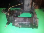
Wondering if anyone has a picture of how this is supposed to be setup? I'm pretty sure I'm missing a connection and a T-valve but I'm not sure. I've stared at multiple parts diagrams and can't find anything that shows these things connected. The system is a few check valves, 1 atop the motor, 2 on the lower block and one maybe halfway up on the port side. THanks for any information you can provide. I'm pretty sure many of the different merc from that era have a similar setup.

Theres also a fitting on the sound attenuator plate near the bottom.

Found another picture. We're getting somewhere now! Although that crankcase doesn't have the 3rd valve top middle of crankcase.
 

Attachments

  • $(KGrHqFHJFQFEMbLcnqJBRDwkqO3Bg~~60_12.JPG
    $(KGrHqFHJFQFEMbLcnqJBRDwkqO3Bg~~60_12.JPG
    34.1 KB · Views: 0
  • setup.JPG
    setup.JPG
    47 KB · Views: 0

MassillonBuckeye

Chief Petty Officer
Joined
Jul 26, 2010
Messages
400
Re: 1979 70HP crank case bleeder valve configuration

Anyone? :( 
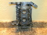
Service manual just says to reconnect them if you disconnect them while disassembling the crank case.

Bottom crank case valve: was able to suck out a decent amount of gas/oil. Others valves seem to be working, just need to know which plumbs to which.

I wear I've searched and searched, checked related and all but now looking under my thread at the "related topics" I've found this thread:
http://forums.iboats.com/mercury-ma...e-bleeder-lines-go-1979-70hp-merc-113454.html

Which basically says:
seem to remember 3 bleed fittings on this motor....the top an bottom are hooked together [lower main to uppermain] and the middle fitting, on the throttle/shift cable side of crankcase goes to the bottom of the airbox in front of the carbs.....or maybe you have 2 middle fittings, the are T'eed together and run to the air box.....

I think we got er. I was worried about that upper cylinder and it wasn't hooked up properly. Now hopefully I'll have less gas mix puddling in my splashwell eating at the sealant.

*Don't mind me, I'm not really talking to myself! Really! I'm not! You you are! NO I'M NOT!
 

MassillonBuckeye

Chief Petty Officer
Joined
Jul 26, 2010
Messages
400
Re: 1979 70HP crank case bleeder valve configuration

Still looking for a pic or diagram. Factory service manual doesn't really say. Here's how they are currently connected and I'm not seeing any gas/oil travelling between #1 and #2. The tubing I used is yellow translucent and still clean. I'd really love to find a picture of an unmolested 3cyl merc from this era to see how they are plumbed. Anyone? Thank you.

bleed valves.jpg
 
Top