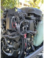
Wiring diagram for 2002 mercury 90 hp

Status
Not open for further replies.

Ebrooker007

Cadet
Joined
Dec 3, 2012
Messages
19
I have a 2002 mercury two stroke I'm finishing up on a rebuild and I have a few wires that I'm not sure how they hook up. I have a diagram but I don't think it is the right one. A wiring diagram would be greatly appreciated. The serial number is OT481533.
 

carholme

Rear Admiral
Joined
Sep 4, 2010
Messages
4,845
Re: Wiring diagram for 2002 mercury 90 hp

If you send me a PM with an email address, I can send you the manual for your engine.

Gerry
 

Texasmark

Supreme Mariner
Joined
Dec 20, 2005
Messages
14,559
Geez....whadda mess!!! Looks like the solenoid pitted and welded at the pits causing the starter to remain engaged which did ok till wiring in the starter overheated, melted the insulation, shorting out internally and continuing the high current demand from the battery to continue uninterrupted. Surprised the battery didn't explode.
 

Texasmark

Supreme Mariner
Joined
Dec 20, 2005
Messages
14,559
Rectifier/reg failed....
Geez another brain fart.....getting too frequent.

With your reply, I looked at the picture again and see that the rect-regl has a hole blown in it and the wire from the starting to the solenoid is burned where adjacent to the input battery wire, but looking on towards the starter, it's intact, indicating to me that I was chasing the wrong rabbit.

So I guess a diode shorted out, one of the grounded ones and put a direct short to ground of the battery voltage.
 

Texasmark

Supreme Mariner
Joined
Dec 20, 2005
Messages
14,559
Yup.........View attachment 332649

Gotta add a fuse in the rec/reg's red output wire that connects to the battery/solenoid , $1 fuse (and a BIGGER law suit) would have prevented this!


I'm sure thread cops are on their way for posting to this old of thread BUT....call it a PSA?
Fuse is 20 amp but not sure it would have prevented the problem. Reason being, there are 2 red wires emanating from the module with the smaller one being power"input" from the battery....aka one terminal of the starting solenoid.....(12v distribution point).... which is a low current requirement for operating the regulator portion of the module. The other, larger wire, "output" from the regulator, goes back to the same starting solenoid terminal as a power input source to the 12v input (from the battery)/distribution point to recharge the battery. This larger wire is pigtailed with an additional, "20A fused" wire that is the 12v output from the engine charging circuit and battery for powering whatever needs 12v power.

A shorted diode in the bridge, one of the two connected to the bridge DC voltage output terminal in the rect-regl could yield a direct path through the regulating device, for the battery's + terminal to see ground through the module. As a resuly, no telling how low the resistance of the module, nor high the current.....Boom!
 

sam am I

Commander
Joined
Jun 26, 2013
Messages
2,169
@Texasmark

The second red wire (un-fused) that also connects to the same 12V battery point (or further down steam) as the other red (fused?) output power wire, is called the sense wire (local or remote).

As designed intentionally, sensing is done with at high input impedance level. As the sense wire enters the rec/reg unit it is wired/protected through a 10K/100K resistor for example.......Therefor, if the rec/reg module has a catastrophic failure and if any active or passive circuity internal to the module shorts to ground (as in our case here did) AND if the failure becomes internally in contact with or even near the sense wire, by nature/design, it is current limited.

12V/10K = 1.2 mA........Hence no fuse required, it's "intrinsically safe" by design.

As where in the case of the (fused?) output wire, by nature/design it CAN'T be a high impedance (outputs are by nature low impedance), if a failure occurred internally to or near ground on this wire...........

12V/0.01ohms = 1200A......Hence fuse required and as seen on the newer merc rec/reg's, BUT only required on this wire.

This (above) relates only to failures in the rec/reg..........which is what we ASSUME happened.

HOWEVER.......

Any and all wires connected directly to a battery source (which both the rec/reg's output and sense are) that run over some xx distance (ABYC reg here) MUST also be fused in the event the wire ITSELF leading from this battery connection shorts at or near ground.


If ran in "remote" mode.............Mine runs like 5' away to my pro-mariner, so it's fused with a 1 amp fuse.

In local mode, the sense wire only needs a run like maybe 6" so no fused is required according to the ABYC reg if memory serves.
 
Last edited:

Texasmark

Supreme Mariner
Joined
Dec 20, 2005
Messages
14,559
@Texasmark

The second red wire (un-fused) that also connects to the same 12V battery point (or further down steam) as the other red (fused?) output power wire, is called the sense wire (local or remote).

As designed intentionally, sensing is done with at high input impedance level. As the sense wire enters the rec/reg unit it is wired/protected through a 10K/100K resistor for example.......Therefor, if the rec/reg module has a catastrophic failure and if any active or passive circuity internal to the module shorts to ground (as in our case here did) AND if the failure becomes internally in contact with or even near the sense wire, by nature/design, it is current limited.

12V/10K = 1.2 mA........Hence no fuse required, it's "intrinsically safe" by design.

As where in the case of the (fused?) output wire, by nature/design it CAN'T be a high impedance (outputs are by nature low impedance), if a failure occurred internally to or near ground on this wire...........

12V/0.01ohms = 1200A......Hence fuse required and as seen on the newer merc rec/reg's, BUT only required on this wire.

This (above) relates only to failures in the rec/reg..........which is what we ASSUME happened.

HOWEVER.......

Any and all wires connected directly to a battery source (which both the rec/reg's output and sense are) that run over some xx distance (ABYC reg here) MUST also be fused in the event the wire ITSELF leading from this battery connection shorts at or near ground.


If ran in "remote" mode.............Mine runs like 5' away to my pro-mariner, so it's fused with a 1 amp fuse.

In local mode, the sense wire only needs a run like maybe 6" so no fused is required according to the ABYC reg if memory serves.
I agree on the sense circuitry being fed by the smaller red wire and it being high enough impedance to prevent problems. What I don't know and assume is that the regulating device is a series pass element, Silicon transistor (probably) or MOSFET and, the mechanism whereby it also shorts out. Guessing an NPN, where the anode is usually reverse biased with positive voltage, grounding that would forward bias the majority of the chip and all that would have to happen would be the EB junction overheat and short out and you'd have your low impedance to ground.........geez, how'd we get off on this.....well it's keeping the cobwebs out of the rusty old brain channels I guess. Grin
 
Status
Not open for further replies.
Top