1988 Merc Black Max 135hp Charging problems

LostInThe80's

Recruit
Joined
Jul 13, 2011
Messages
5
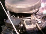
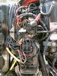
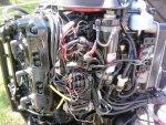
Photo0457.jpgPhoto0453.jpgPhoto0456.jpgGreets to all since this is my first posting here. First a short run up. As I stated in the thread description, I have a 1988 Merc Black Max 135hp Oil Inject motor SN-0B304160. I've been experiencing charging problems in that I'm only getting about 12.4 - 12.7v output with about 1.8 -2.1amps output as well. This is at low speed and medium speed (about 20-25mph). I brought the boat in to get checked and was told my rectifier was shot. I had it replaced. The tech said that there was a hole burnt through it. I got the boat back and tested it on the water. The highest voltage output I measured was about 12.6vdc and the amps were about 2.7. I brought it back to the same shop and told the tech what I found out. She checked the stator for me and said that the high side was at about 130 and that it was a bit low but was still in working order. The low side was at 35 I believe. Apparently the stator had checked out OK. As I asked questions about the charging path, she deduced that there was a secondary rectifier on the top of my engine at the back. She didn't know for sure since she didn't know what this part was exactly. I asked if the part was a voltage regulator but she didn't think so. Can anyone tell me their opinion on the charging problem or this secondary rectifier/regulator? I've attached three pics. The one of the right side view shows the old rectifier assembly obscured before replacement. It's to the left of the solenoid. The top of the engine shows the suspected secondary rectifier or regulator I was talking about. It's to the right of the black box and is the one with the yellow and red wires coming out of the top.
 

j_martin

Admiral
Joined
Sep 22, 2006
Messages
7,474
Re: 1988 Merc Black Max 135hp Charging problems

Fire your tech. She don't even know what to test. She was on one of the switchbox charge coil sets.

The device on the switchbox mounting plate is a bridge rectifier. One terminal is labeled +. The other two are stator connections. Make sure it's hooked up right. There's a FAQ on this site that has testing procedure for it.

The device on the top is a stator saturation regulator. It is NLA, probably because it's value is somewhere between useless and hazardous. (as in fire starting) If it's shorted it would take out a mercury rectifier in a heartbeat. If you put in one with decent parameters (ie radio shack 20 amp bridge rectifier) it wouldn't blow, but would probably ignite the regulator.

1. disconnect and test the rectifier with an ohmmeter and the FAQ I referred to. Replace if bad.
2. Measure the resistance between the yellow wires. It should be less than 1 ohm, but not 0. There should be no continuity (infinite resistance) between either yellow and ground.
3. When you re connect the rectifier, make sure the wires are on the right terminals.
4. Disconnect the regulator, at least for now, probably permanently.

If the stator is bad, it needs to be replaced.
Options from there
1. Install a fresh murkery rectifier, might as well stock spares.
2. Fit a better bridge rectifier.
3. Install a 16-20 amp regulator, commonly used on later engines in pairs. You only need one.

If you don't install a regulator, the battery will do the job. It will use some water doing it. If it is regularly maintained, it's life will not be shortened.

hope it helps
john
 

LostInThe80's

Recruit
Joined
Jul 13, 2011
Messages
5
Re: 1988 Merc Black Max 135hp Charging problems

Thank you sir for the quick reply. I will go outside and do this now.
 

LostInThe80's

Recruit
Joined
Jul 13, 2011
Messages
5
Re: 1988 Merc Black Max 135hp Charging problems

Alright then. If I got the right FAQ (Small Rectifier Test by Joe Reeves) here's how it went with pics too. I started out by checking the voltage at the new rectifier. I guess no photos since I can only have 5 per post. Here's the details:

12.95vdc at the "+" terminal - I fully charged the battery prior to this. Completely segregatred as well.

Wires removed from rectifier. With ground probe on rectifier base all readings were 0 or OL. I then reversed wires placing the red probe on the base. I got a reading of .791 ohms on the terminal with two yellow wires. Zero on the other two.

Next was your resistance test between the yellow wires. I received a reading of .3 ohms when connected to the actual yellow wires themselves but zero when connected to the yellow wire's teminals.

I tested the Saturation Regulator and these are the readings I got:

18.07 Meg Ohms connected across the terminals in one direction. Zero reversed. With the ground probe on it's housing and the red connected to the right terminal I got a reading of 14.76 Meg Ohms. When I touched the red probe to the other terminal I got a reading of .825 Meg Ohms. This was just in case you needed their values.

I reconnected the rectifier wires to their original locations. You stated to disconnect the regulator at least for now, probably permanently. This was the aforementioned stator saturation regulator on top of the motor correct? If I understood you right, the battery will assume the role of the stator saturation regulator if this is disconnected?
 

j_martin

Admiral
Joined
Sep 22, 2006
Messages
7,474
Re: 1988 Merc Black Max 135hp Charging problems

Did you check to see if the wires were in the right location to start with? Red to +, yellow to the other 2.

The battery will hold the voltage down. It won't introduce DC into the stator winding to magnetically saturate the core.

0 and OL are different readings. One is a dead short, and one is infinity. If you used a diode test setting, the .791 is a normal forward junction voltage on a silicon rectifier, which is what this is.
Look up the diagram for a bridge rectifier, and check with a meter for normal forward voltage drop, and no current (OL or infinity with an ohmmeter) in the other direction on each diode. There's 4 in a bridge rectifier.

It sounds like you have a shorted rectifier. The stator is fine.

The regulator is an active circuit. External measurements with an ohmmeter are useless. Just disconnect it.

Upload your photos, trimmed to 600 pixels in the max dimension to photobucket.com, the use the insert image tool to put them into your post. Should be no limit within reason.
 

j_martin

Admiral
Joined
Sep 22, 2006
Messages
7,474
Re: 1988 Merc Black Max 135hp Charging problems

It's obvious you don't know how to test the rectifier.

Never mind the regulator for now. Leave it disconnected till you get the rectifier fixed.

Here's Joe Reave's version of small rectifier test.

http://forums.iboats.com/showthread.php?t=190638

Note that when he says no reading, he means open, infinity, OL.

When he says lower reading, he means higher resistance. (he's thinking current)

When he says a resistance reading, he means something other than 0 or infinity.

Test it and come back.
 

LostInThe80's

Recruit
Joined
Jul 13, 2011
Messages
5
Re: 1988 Merc Black Max 135hp Charging problems

Sorry for the delay. I had a rain delay. I took this into consideration but went in a different direction with my testing. I decided to test the outputs with the motor running with the regulator connected and disconnected. I first took a close look at all the connectors and connections that I was working with and cleaned them up real good. Some looked a little borderline. I started this block of tests with the voltage regulator disconnected.

-With the engine running at the lowest idle I measured 13+ volts dc and 2.8-3.05 amps fluctuating. Voltage was slowly increasing.

-Idle was increased to about 1000 rpm's and the voltage climbed to 14.8vdc with nearly 4 amps output. Voltage and amperage were slowly increasing.

-I then increased the rpm's to about 1200 and measured 15.9vdc and 4.5 amps. Both voltage and amperage were slowly increasing.

-I then increased the the idle speed to about 1500 rpm's. The voltage measured 16.6vdc and the amps were at 5.8. Both were slowly increasing.

-At this point I decided to drop back down to the lowest idle so I didn't overcharge the system without a regulator in the circuit. I shut down the engine and let it sit for 5 minutes to check the charging capacity of the battery. It started at 13.58vdc and dropped to a rather steady 13.04vdc after 5 minutes. This is about what I understand the system should function at. Battery checked out.


2nd Test.

For this test, I re-connected the voltage regulator into the circuit and started the motor. I began this test at 15:45

-At the lowest idle I measured 12.8vdc and about 1.8-2.2 amps output. The voltage ever so slowly started to increase. It increased about a tenth of a volt per 30-40seconds.

-I increased the rpm's to about 1000. I measured 2.81+ amps (fluctuating) with 12.96vdc. Both were slowly increasing.

-15:50 - 12.99vdc and 2.83-2.92 amps output.
- I increased the rpm's to about 1500. I measured 13.07vdc holding steady with 3.55 amps output.

-15:55 - At 1500 rpm's I measured 13.27vdc with 3.62 amps output slowly increasing.

-16:00 - 13.35vdc and 3.65 amps output. I returned the rpm's back to the lowest idle setting. The measured voltage dropped to 12.98vdc and continued to drop slowly. The amperage was measured at 1.96-2.06 amps.

- I began the capacity check at this time and measured 12.96vdc.

-16:05 - Voltage measured 12.95vdc. Battery good.

By what I've tested, it seems that the voltage regulator's resistance is getting higher and it's output is degrading. It seems to me that my problem is my regulator. Another blogger said to test the output voltage at the rectifier's red wire to see if there was any AC voltage present and that if there was the rectifier wasn't working right. I don't know if there was any validity to this but I tried it anyway. There was none so it appears that the rectifier is doing it's job. If the VR's bad, I can replace it or buy a newer and bigger marine battery to regulate the voltage for me. What if the voltage goes higher than the 16+ volts? Won't this damage the system or electronics?
 
Top