1980 Thunderbolt 1150 No Fire

RayRob

Cadet
Joined
Jun 27, 2010
Messages
14
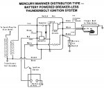
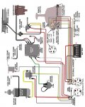
Greetings all. I'm new to this forum and have a Question I'm pretty sure has been covered before but here goes... I have a 1980 Merc. 115(1150) w/ "thunderbolt ignition". Ie: distributor and coil. When I bought it it did not run but turned over. 135 compression across all cyl. Some threads say bad switch box, OR stator, Or coil etc...
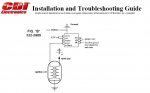
Is there a set of simple troubleshooting test to eliminate each component?
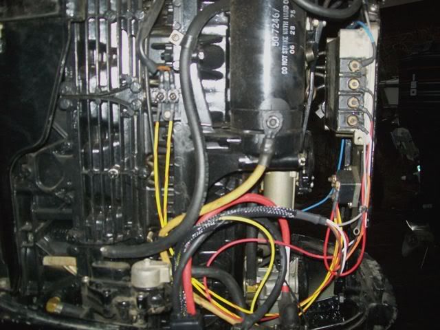
I have no fire to any plug. Have 12vdc to switch box (wht wire) .
Any and all help would be appreciated.
 

Moody Blue

Captain
Joined
May 24, 2004
Messages
3,136
Re: 1980 Thunderbolt 1150 No Fire

Can you post a S/N for your motor. With distrib and single coil, I doubt you have a 1980 motor.

There must also be +12 at the RED wire on the port side of the switchbox.

Is there a kill switch anywhere on the boat?

Disconnect the mercury tilt switch on the off chance it's defective.

Read here for troubleshooting guides

http://www.boatpartstore.com/page18.asp
http://www.maxrules.com/cdi/TroubleshootingGuide.pdf
http://dolphinmarineservice.homestead.com/tech.html
 

RayRob

Cadet
Joined
Jun 27, 2010
Messages
14
Re: 1980 Thunderbolt 1150 No Fire

Can you post a S/N for your motor. With distrib and single coil, I doubt you have a 1980 motor.

There must also be +12 at the RED wire on the port side of the switchbox.

Is there a kill switch anywhere on the boat?

Disconnect the mercury tilt switch on the off chance it's defective.

Read here for troubleshooting guides

http://www.boatpartstore.com/page18.asp
http://www.maxrules.com/cdi/TroubleshootingGuide.pdf
http://dolphinmarineservice.homestead.com/tech.html

S/N 4396252 Matches title says 1980.
no red wire going to switch box.
has old mercontrol set. I don't know about a kill switch.
No mercury tilt switch. Thanks
 

Moody Blue

Captain
Joined
May 24, 2004
Messages
3,136
Re: 1980 Thunderbolt 1150 No Fire

From the info I have, you have a 1976 model.

CHeck here

http://store.eastcoastmarineservice.com/category_s/882.htm

http://store.eastcoastmarineservice.com/category_s/2687.htm

http://www.maxrules.com/Merc_model_files/115-150.html

I believe the ignition systems changed in 1979 to do away with the distributor.

This should be the wiring diagram for your motor. You need a constant +12V at the RED terminal on the PORT side of the switchbox (see diagram), AND switched +12V at the WHITE wire on the port side.

http://www.maxrules.com/oldmercs/Wiring/1966ona/50.jpg
 

RayRob

Cadet
Joined
Jun 27, 2010
Messages
14
Re: 1980 Thunderbolt 1150 No Fire

Thanks MB, I'm now convinced that it is a '76 model.:)
However, the wiring harness seems as though it had been replaced (new looking). there is not a red wire going into or out of switch box. the only wires are brown, cream, black = to dist.
white into switch box.
green to coil.
switch box part #cdi 114-2986
also stator wires from the stator read -50 ohms
when i hook up the leads from rectifier to stator it seems to ground out (0.00ohms)s :confused:
 

Chris1956

Supreme Mariner
Joined
Mar 25, 2004
Messages
27,158
Re: 1980 Thunderbolt 1150 No Fire

Well, That ign system needs +12VDC to fire. Next to the white wire to the switchbox should be a red wire that connects to the boat harness and the rectifier.
 

RayRob

Cadet
Joined
Jun 27, 2010
Messages
14
Re: 1980 Thunderbolt 1150 No Fire

Thanks for the reply.
I have a red +12v wire coming from harness to rectifier. One wire shows voltige
going to stator and one wire grounded (-).
 

achris

More fish than mountain goat
Joined
May 19, 2004
Messages
27,468
Re: 1980 Thunderbolt 1150 No Fire

This should help you....
attachment.php
 

Attachments

  • Battery CD ignition system (small).jpg
    Battery CD ignition system (small).jpg
    98.2 KB · Views: 1

RayRob

Cadet
Joined
Jun 27, 2010
Messages
14
Re: 1980 Thunderbolt 1150 No Fire

Thanks for the diagram. My switch box has no place to hook a red lead to.
The white wire connects to a white w/ red stripe wire. my red lead goes to rectifier.
 

Moody Blue

Captain
Joined
May 24, 2004
Messages
3,136
Re: 1980 Thunderbolt 1150 No Fire

Can you confirm that the switchbox you have has 3 terminals on the distributor side AND 4 terminals on the non-distributor side?

What color wire is connected to each of the terminals?

The attached diagram SHOULD represent your motor.
 

Attachments

  • 115.jpg
    115.jpg
    85.7 KB · Views: 0

RayRob

Cadet
Joined
Jun 27, 2010
Messages
14
Re: 1980 Thunderbolt 1150 No Fire

Very similar except that there is no mercury switch and no red lead at switch box. "However, the wiring harness seems as though it had been replaced (new looking). there is not a red wire going into or out of switch box. the only wires are brown, cream, black = to dist.
white into switch box.
green to coil.
switch box part #cdi 114-2986"
 

75TowerOfPower

Petty Officer 1st Class
Joined
Apr 17, 2009
Messages
331
Re: 1980 Thunderbolt 1150 No Fire

Ok on the other side of the switch box should be the ignition wire. So thats where is the 12V should be.
 

ClassyGlassy

Petty Officer 1st Class
Joined
Feb 21, 2010
Messages
383
Re: 1980 Thunderbolt 1150 No Fire

I happen to have a jumper wire from the red wire on the rectifier to the red post on the switchbox..............

Boat084.jpg
 

RayRob

Cadet
Joined
Jun 27, 2010
Messages
14
Re: 1980 Thunderbolt 1150 No Fire

The white wire from harness to switch box is +12vdc. it connects to the white w/ red stripe wire. the switch box is a CDI- Rapair box # 114-2986 if that helps. Can you tell me what the voltage is on the two wires going to stator?
I have current on one side+ and (-) one the other. I have +12 going in to rectifier.
 

achris

More fish than mountain goat
Joined
May 19, 2004
Messages
27,468
Re: 1980 Thunderbolt 1150 No Fire

I have just had a look at CDIs webpage for 'Installation and Troubleshooting' of this switchbox, HERE, and I must say that it leaves me a little concerned. They appear to be a bunch of idiots who can't even draw a circuit properly, so how can anybody expect them to design and make a switchbox with any confidence?

This is the diagram in the guide that raised my attention.

attachment.php


First glance and I see 3 things wrong...

1. Battery wire connected to ground. Hmmm.... I can see that ending in smoke and tears.
2. Red and White terminals shown jumped together. Really bad idea. And where is the ignition switch?
3. This is just a convention (used by every electronics tech in the world!!!). Grounds should NEVER be drawn upside down. This is the sort of crap that is taught in 1st year courses. Obviously these guys don't go to courses either.

This is why I always prefer OEM. If they can't get these basics right how the he!! do they build anything that would work?

Chris.........
 

Attachments

  • CDI diagram.jpg
    CDI diagram.jpg
    42.7 KB · Views: 0

ClassyGlassy

Petty Officer 1st Class
Joined
Feb 21, 2010
Messages
383
Re: 1980 Thunderbolt 1150 No Fire

Hey Rob, I'll go out and check right quick......those wires coming down from the stator, yellow/red, are probably only going to have voltage on one side until the engine is running.....they are the voltage created by the stator to charge the battery, etc?
 

ClassyGlassy

Petty Officer 1st Class
Joined
Feb 21, 2010
Messages
383
Re: 1980 Thunderbolt 1150 No Fire

OKay, I have 0v at both the yellow/red wires coming down from the stator. I have 12v at the red wires and 12v at the white wire.
 

achris

More fish than mountain goat
Joined
May 19, 2004
Messages
27,468
Re: 1980 Thunderbolt 1150 No Fire

The white wire from harness to switch box is +12vdc. it connects to the white w/ red stripe wire. the switch box is a CDI- Rapair box # 114-2986 if that helps. Can you tell me what the voltage is on the two wires going to stator?
I have current on one side+ and (-) one the other. I have +12 going in to rectifier.

Despite what CDI have tried to tell me in the past, the ignition system and the charging system are completely separate. And that will remain the case!

You should have 2 yellow wires going from the stator under the flywheel to the rectifier. You should have a red wire going from the rectifier to (eventually) the positive on the battery. This is the charging system. You also need a red wire going from the battery to the 'red' terminal on the switchbox. ClassGlassy has done that by running the red from the rectifier, but the resultant circuit remains the same, the 'red' terminal on the switchbox has a constant 12 volts at all times. The white should only have 12 volts when the ignition key is on.

Chris............
 

ClassyGlassy

Petty Officer 1st Class
Joined
Feb 21, 2010
Messages
383
Re: 1980 Thunderbolt 1150 No Fire

Chris is right, of course, and I ran the jumper wire because when I purchased the new CDI engine harness that's what the drawing said to do that came with it.
 

achris

More fish than mountain goat
Joined
May 19, 2004
Messages
27,468
Re: 1980 Thunderbolt 1150 No Fire

Chris is right, of course, and I ran the jumper wire because when I purchased the new CDI engine harness that's what the drawing said to do that came with it.

Sort of backs up my belief that they really don't have a clue about engines...

In the original harness there is a red wire specifically for the switchbox. Electrically it's the same wire as the one on the rectifier... and you shouldn't have needed to run a new one. The harness in your picture looks a little non-genuine, and really neat :D. Did you do it yourself?

Chris......
 
Top