edit-Insert
Seaman Apprentice
- Joined
- May 22, 2017
- Messages
- 34
This motor was last registered in 2007. The following are item I have done to see if it worth buying parts and repairing or just trying to source a new to me power plant.
- Replace fuel lines from tank to motor.
-Check plugs and wires.
- bypass mercury switch as it was damaged.
- bypass 12v onboard battery wiring with jumper cables due to the aweful condition existing were in.
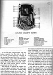
I've got twelve volts from ignition when disconnected from the coil housing. Once connected it drops to 8. When cranking it drops to 4 or 5. I grounded the #3 plug just to see if I had even a weak spark. No joy. I removed the coil housing and dizzy. Once open it smells similar to a burnt circuit board. Can I replace just that part that looks like it has been plasti-dipped or do I need to replace everything inside of it?
The rotor cap and button and all contact points looks dirty from use but none were burnt.
I intend on making my own wiring harness using a car amplifier wiring kit. They're much cheaper and I have plenty of low voltage experience. Will the copper clad aluminum wire suffice for this or must it be true copper braid?
Does anyone have a high resolution print of the ignition system? All I can find is low res and I'm not certain it's even the right diagram because I can't read anything on the prints.


