you can assume all you want but the white/green stripe is usually connected to the dist on one end or the neg side of the coil and the end in the pic is connected to the shift interrupter.
The heavy black usually goes to a mounting bolt on the alt casing for the ground.
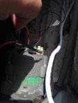
Ok so I cleaned up some of the dodgy wiring. The white with green stripe that was loose I tied into the wire that was already going from the coil to the interrupter. I'm not sure if this is correct so I made it so I can separate it. Lease look at the pics and let me know what you think.
remove that connection, the white W/ the green stripe most likely already goes to the dist already(if electronic) and to the neg side of the coil if points.
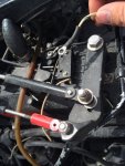
In the second pic, the screw to the right is a mounting screw that also acts as the ground side. the screw to the left is isolated and has no connection to ground.
it looks like there are 2 wires already on that screw. start the motor and activate the switch to see if the motor stalls or shudders.
in post 2 pic 2 there is a brown wire that looks like it goes to the coil. is should be going to the yellow arrow screw, the other end of the switch should be going to the other screw. the white/ w green goes to the yellow screw .. it is connected to the grey tach wire in the harness , and that will ground the ign coil when shifting out of gear.
The PO had the longblock replaced with a new one a couple years ago so I don't think the serial number will help much. The electrical is original from the 88 setup. I'll compare the wiring map you posted to what I have and let you guys know.