


San_Diego_SeaRay
Petty Officer 1st Class
- Joined
- Nov 9, 2014
- Messages
- 337
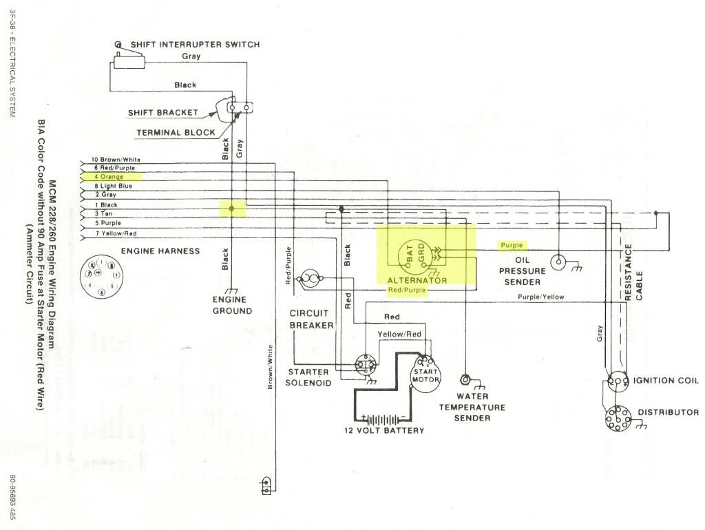
As you might know from my previous posts, I'm basically rebuilding a 1981 Mercruiser MCM 260. Was mostly dismantled when I bought her so I've been having to do some detective work on how to reassemble it. I'm now at the "electrical phase" and am a bit stumped about some of it. OK, I'm actually stumped at the very beginning of it so you might say that so far I'm stumped on all of it. 
I bought an aftermarket marine AC Delco 10SI Alternator that has two wires and a "BAT" terminal and puts out 105 amps; significantly more than than the OEM alternator.
The attempt at my understanding (things I think I might have figured out):
JC in SD
I bought an aftermarket marine AC Delco 10SI Alternator that has two wires and a "BAT" terminal and puts out 105 amps; significantly more than than the OEM alternator.
The attempt at my understanding (things I think I might have figured out):
- The purple wire that connects to the #5 terminal on the harness plug and is wired in parallel w. the "+" coil wire is the exciter wire (black wire on my alternator)
- The red/purple wire that is connected to the circuit breaker is the "sense" wire and ultimately detects voltage of the + side of the battery
- The "BAT" terminal is wired to the #4 terminal on the harness plug and....well...I don't know what it does
- Why would there be a circuit breaker in a dedicated sensing wire circuit? (It makes me think that this is not a sensing wire circuit)
- I thought that the "BAT" terminal supplied the amps to recharge the battery. Instead, the only wire at this terminal is a smallish orange wire that is routed to the harness plug. I would imagine there should be a heavy gauge wire that gets routed to the battery from this terminal. Definitely not a small wire into a harness plug.
- Is the alternator grounded to the engine block? If so, what is the purpose of routing a ground wire out of the alternator and putting it in a parallel junction w. harness plug terminal #1, the shift interrupter, and the starter relay (which are already tapped into the engine ground)? The reason I ask is because I'm not sure my alternator has a ground terminal per se and I'd rather avoid the subject if I can.
- I'm also wondering about the ramifications of buying an "oversized" alternator.
- Why does my tech manual mention diagram models with and without a 90 amp fuse? (My engine does not have a 90 amp fuse). Is this a safety concern?
- I was thinking of installing an ammeter for the enjoyment of watching another needle on another gauge. Would this facilitate installing a 90 amp fuse at the same time if advisable?
JC in SD
Last edited:
