Quicksilver Remote Control Wiring

g_speran

Seaman
Joined
Jul 6, 2008
Messages
62
Hello ALCON,
I am looking for some assistance on wiring my QuicSilver Remote Control. I do not know what model it is. The boat is a 1987 Sunbird Corsair. I have attached the pic below.

IMAGE1.jpg

TIA,
Gary
 

Don S

Honorary Moderator Emeritus
Joined
Aug 31, 2004
Messages
62,321
Re: Quicksilver Remote Control Wiring

Who the heck is ALCON ?
 

g_speran

Seaman
Joined
Jul 6, 2008
Messages
62
Re: Quicksilver Remote Control Wiring

:) Its a military term.. ALL CONCERNED (ALCON)
 

g_speran

Seaman
Joined
Jul 6, 2008
Messages
62
Re: Quicksilver Remote Control Wiring

Also, can one tell me what type of trim solenoid I can purchase from iboats to replace my non functioning UP/OUT solenoid? The trim pump is a SAE J1171 Marine.

TIA,
Gary
 

Don S

Honorary Moderator Emeritus
Joined
Aug 31, 2004
Messages
62,321
Re: Quicksilver Remote Control Wiring

That SAE J1171 is not a part number for a pump. It's a spec. number that says it's Ignition Protected and safe and approved for use in the engine compartment of a boat.

The OEM part number for the trim solenoid is 89-96158T, the Sierra number that iboats has is 18-5817

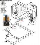
Here is a picture that should explain the wiring. From this thread http://forums.iboats.com/showthread.php?t=391526

attachment.php
 

stonyloam

Vice Admiral
Joined
Mar 13, 2009
Messages
5,827
Re: Quicksilver Remote Control Wiring

That would be a commander side mount control.
 

g_speran

Seaman
Joined
Jul 6, 2008
Messages
62
Re: Quicksilver Remote Control Wiring

Does anybody know where to get the trim switch and trailer switch from? I am not necessarily looking for part #18286T33. Trying to keep cost down as much as possible. So if you know of a location that just sells the switches, that would fit in this commander side mount remote control, please let me know.

TIA,
Gary
 

stonyloam

Vice Admiral
Joined
Mar 13, 2009
Messages
5,827
Re: Quicksilver Remote Control Wiring

Hmmmm just exactly what is your problem? If the trim and trailer switches are not working it is FAR more likely that you have a problem with the up trim solenoid especially if the down switch works. Don how about your trim troubleshooting page?;)
 

g_speran

Seaman
Joined
Jul 6, 2008
Messages
62
Re: Quicksilver Remote Control Wiring

OK, so being absolutly new to boating and using this forum to troubleshoot all the issue I have been encountering with this project boat, how important is it to have the Trim Sender and Trim Limit switches actually connected? I currently have the lower unit removed off the boat as I had to replace the water pump in the lower unit. Therfore the trim switches are not connected to the bell housing. If they need to be connected, is there a way to simulate them bing connected without actually connecting them or the lower unit?

TIA,
Gary
 

stonyloam

Vice Admiral
Joined
Mar 13, 2009
Messages
5,827
Re: Quicksilver Remote Control Wiring

Ok you probably do not want to mess with the trim with the outdrive off and the trim rams disconnected, because if you run the pump you can take the rams to their limit and there is the possibility they could jam or at least move to a point that it is difficult to reattach them to the outdrive. The starboard switch just goes to the trim gauge and has nothing to do with trim operation. The port side switch is the trim limit switch that controls the maximum up trim of the outdrive, and must be connected and in the correct position for the trim up switch to work. The trailer switch should work with the outdrive in any position and is not affected by the trim limit switch. The trim down switch should work anytime it is pushed. There are two solenoids that control trim, one for up and one for down. So if both you trim and trailer do not work and the down does, chances are that it is the up solenoid rather than the switch which rarely fail. My advice is don't mess with the switches or trim until you have everything back together with the rams attached, then come on back and we can get you working properly. To answer your question, yes you can bypass the switch. Good luck.
 

g_speran

Seaman
Joined
Jul 6, 2008
Messages
62
Re: Quicksilver Remote Control Wiring

Also…here are some test I have already done. Based upon the test conducted below. I believe that my switch is good as well as the wiring..Now :). Firmly believe that my up solenoid is bad. Figure since I am going to replace on, I might as well replace both at the same time.

Any recommendations on testing the trim switches to see if they are OK?

1. Trim Pump Motor test
a. Connect a jumper wire between positive (+) solenoid terminal and BLUE/WHITE motor lead terminal – Results….motor ran
b. Connect a jumper wire between positive (+) solenoid terminal and GREEN/WHITE motor lead terminal – Results….PASSED ….motor ran

2. Solenoid Test
a. Connect jumper wire between positive (+) solenoid terminal and BLUE/WHITE harness wire terminal. Results…FAILED…Only clicking noise from Solenoid
b. Connect jumper wire between positive (+) solenoid terminal and GREEN/WHITE harness wire terminal. Results… PASSED ….motor ran

3. 110 AMP Fuse Test
a. Check for voltage at terminal “1” using a volt meter. Voltage MUST BE indicated before proceeding with next check. – Results….PASSED…Voltage received
b. Check for voltage at terminal “2,” using volt meter. – Results….PASSED…Voltage received

4. Solenoid Harness test (Image attached IMAGE1)
a. Connect a jumper wire on bottom terminal (Red) to left terminal (Blue). Results… Results…FAILED…Only clicking noise from Solenoid
b. Connect a jumper wire on bottom terminal (Red) to top terminal (Green). Results… Results… Results….PASSED ….motor ran
NOTE: Above test is only to prove to me that there is solid connection from the harness to the solenoid switches.

5. Switch to Control Arm Harness Test (Same Wire Test IMAGE2)
a. Connect a jumper wire on Red terminal at trim button to Red terminal at Control Arm harness (Bottom) - Results…PASSED…20 ohms received
b. Connect a jumper wire on Blue terminal at trailer button to Blue terminal at Control Arm harness (Right) - Results…PASSED…20 ohms received
c. Connect a jumper wire on Green terminal at trim button to Green terminal at Control Arm harness (top) - Results…PASSED…20 ohms received
d. Connect a jumper wire on Purple terminal at trim button to purple lead bullet connector.(end that connects to trim switch) - Results…PASSED…20 ohms received
NOTE: Above test is only to prove to me that there is solid connection from the switch to the end of the male connectors in the harness (For purple to the end of the lead bullet connector.

6. Switch Only Test
a. Connect a jumper wire to the Red wire on the trailer button and Green Wire (Out/Up) on the trim rocker. Toggle rocker DOWN…. Results….PASSED …. 25 ohms received
b. Connect a jumper wire to the Red wire on the trailer button and Purple Wire (In/Down) on the trim rocker. Toggle rocker UP…. Results….PASSED …. 25 ohms received
c. Connect a jumper wire to the Red wire on the trailer button and Blue Wire (Out/Up) on the trim rocker. Push Trailer button in…. Results….PASSED …. 25 ohms received
NOTE: Above test is only to prove to me that the switch is good.

7. Switch and Control Arm wire test (Switch & Control Arm lead bullet connectors connected)
a. Connect a jumper wire to the Red bullet connector and Green bullet connector (Out/Up) on the trim rocker. Toggle rocker DOWN…. Results….PASSED …. 25 ohms received
b. Connect a jumper wire to the Red bullet connector and Purple bullet connector (In/Down) on the trim rocker. Toggle rocker UP…. Results….PASSED …. 25 ohms received
c. Connect a jumper wire to the Red bullet connector and Blue bullet connector (Out/Up) on the trim rocker. Push Trailer button in …. Results….PASSED …. 25 ohms received
NOTE: Above test is only to prove to me that that there is continuity from the switch to the beginning of Control arm wires

8. Switch and Control Arm Harness test (Switch & Control Arm lead bullet connector connected)
a. Connect a jumper wire to the Red wire on the trailer button and Green terminal at Control Arm harness (top) - Results…PASSED…20 ohms received
b. Connect a jumper wire to the Red wire on the trailer button and Purple lead bullet connector.(end that connects to trim switch) - Results…PASSED…20 ohms received
c. Connect a jumper wire to the Red wire on the trailer button and Blue terminal at Control Arm harness (right) - Results…PASSED…20 ohms received
NOTE: Above test is only to prove to me that that there is continuity from the switch all the way thru the end of the male terminals in the Control Arm Harness

9. Control Arm Harness to Control Arm Harness
a. Connect a jumper wire to Red terminal at Control Arm harness (Bottom) to Blue terminal at Control Arm harness (Right) - Push Trailer button in.. Results…PASSED…20 ohms received
b. Connect a jumper wire to Red terminal at Control Arm harness (Bottom) to Green terminal at Control Arm harness (top) - Toggle rocker DOWN… Results…PASSED…20 ohms received
c. Connect a jumper wire to Red terminal at Control Arm harness (Bottom) to Purple lead bullet connector.(end that connects to trim switch) - Results…PASSED…20 ohms received
NOTE: Above test is only to prove to me that that there is continuity from beginning to end of Control Arm Harness
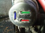
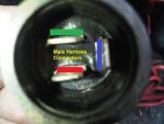
IMAGE1.jpg IMAGE2.jpg

TIA,
Gary
 

stonyloam

Vice Admiral
Joined
Mar 13, 2009
Messages
5,827
Re: Quicksilver Remote Control Wiring

Holy moley! More than I could read LOL. Yeah replace the solenoids, keep the good one for a spare. Ok now to bypass the limit switch to test the control lever switches. Once the new solenoid is in and working. Go the the back of the boat and locate two black wires that come through the transom plate and go to two connectors. One with a purple/white wire and one with two blue/white wires. Unplug the black wires and with a short piece of wire jumper between the two connectors. Try the trim up switch, it should work (bet it will). With the new solenoid your trailer should also work, if so then you are good to go as far as the control switches go. Now did you remove the trim limit (port side) switch? and is it still off?
 

g_speran

Seaman
Joined
Jul 6, 2008
Messages
62
Re: Quicksilver Remote Control Wiring

Unfortunatly, both trim switches are still off. I was hoping to get to install my bellows and lower unit today, but my son want to go race a local BMX race today. So fun with the family. I've been called out of town, so I wount be able to update this thread probably until next Saturday night. By that time, the solenoids I ordered from Iboats should be in.

TIA,
Gary
 

g_speran

Seaman
Joined
Jul 6, 2008
Messages
62
Re: Quicksilver Remote Control Wiring

OK....Report update.

The Solenoids came in and have been installed. I jumped the 2 wires as Stonyloam as suggested and the Up/Out, Down/In, and trailer buttons are now 100% functional. Thank you Don and Stonyloam for your great assistance!!!!

Now for an IDIOT question, as I am still learning. After installing the Solenoids, I went to go use the Up/Out, Down/In, and trailer buttons and they would NOT work. So.. I went back and performed the Trim Motor test...it passed and then I did the Solenoid test and it passed. So after 30-45 minutes of scratching my head, testing wires, throwing tools, and then walking away, I got a "BRIGHT" idea to hook up a battery charger to the battery. As soon as I connected the battery charger, I tested the Up/Out, Down/In, and trailer buttons again....and....woo hoo. It all worked!!!

But for someone like me who is still new to all this, can you tell me why the switches would not work when the battery was low but the solenoid test and the pump motor test both worked with the low battery.

TIA,
Gary
 

stonyloam

Vice Admiral
Joined
Mar 13, 2009
Messages
5,827
Re: Quicksilver Remote Control Wiring

The only logical reason is that there is a higher resistance connection somewhere in the 12V line going to the switches, that causes a little voltage drop, and with the low battery voltage there was not enough to activate the solenoids, but using the short jumper for the test there was a good enough connection. You could check the voltage coming to the solenoids (b/w and g/w wires on small terminals) should be same as battery voltage.
 

g_speran

Seaman
Joined
Jul 6, 2008
Messages
62
Re: Quicksilver Remote Control Wiring

Can you point me to Don S trim troubleshooting page? I have installed all the new bellows and shift cable today. So i have the bell housing reattached to the gimbal ring and have reinstalled the Trim sender and limit switches. I need to adjust those today.

TIA,
Gary
 

g_speran

Seaman
Joined
Jul 6, 2008
Messages
62
Re: Quicksilver Remote Control Wiring

Thanks Don!

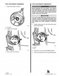
I also located, in the documents that were provided me, on installing and adjusting the trim limit switch. Good thing I checked, because I did not have the index marks aligned on the trim limit switch

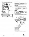
64AR3_p14_Page_13.jpg 64AR3_p14_Page_14.jpg

TIA,
Gary
 
Top