Ballast resistor and coil confusion

Status
Not open for further replies.

redgoat

Petty Officer 2nd Class
Joined
May 23, 2010
Messages
102
After 45 years of running my Sea Ray on a conventional points and condenser ignition, I am installing a Sierra electronic conversion for 4 cyl Delco ignition. My Mercruiser is a 4cyl, 153 cu.in., 120 hp engine. I have got to to the final instruction where I must do something with the red wire from the ignitor. One diagram says to connect the red wire to the positive side of the coil. The other diagram says to connect the red wire to a ballast resistor which is itself connected to the coil. My question is if I had a ballast resistor, wouldn't its presence be noticable near the coil? My coil is a standard oil-filled coil with markings 12v use with external resistor. I have never had a coil issue ever with my old standard ignition. I'm thinking I should just connect the red wire to the positive side of the coil and start the engine. Does this sound correct?
 

Bondo

Moderator
Staff member
Joined
Apr 17, 2002
Messages
70,526
Re: Ballast resistor and coil confusion

After 45 years of running my Sea Ray on a conventional points and condenser ignition, I am installing a Sierra electronic conversion for 4 cyl Delco ignition. My Mercruiser is a 4cyl, 153 cu.in., 120 hp engine. I have got to to the final instruction where I must do something with the red wire from the ignitor. One diagram says to connect the red wire to the positive side of the coil. The other diagram says to connect the red wire to a ballast resistor which is itself connected to the coil. My question is if I had a ballast resistor, wouldn't its presence be noticable near the coil? My coil is a standard oil-filled coil with markings 12v use with external resistor. I have never had a coil issue ever with my old standard ignition. I'm thinking I should just connect the red wire to the positive side of the coil and start the engine. Does this sound correct?

Ayuh,.... Merc uses a resistor Wire, rather than a ballast resistor...

Does the instructions say to hook yer red wire to the battery side of the ballast resistor, or the lower resisted side of it,..??

If it needs a full 12 volts, you need to tap into the ignition circuit, before the resistor wire...
 

redgoat

Petty Officer 2nd Class
Joined
May 23, 2010
Messages
102
Re: Ballast resistor and coil confusion

The instructions say that for installations that do not use a primary ballast resistor, connect the red ignitor to the positive coil terminal. For installations that use a primary ballast resistor, connect the red ignitor wire to the ignition switch side of the resistance. The feedback I read on these electronic ignitions before I bought one was very positive AND they should only take minutes to install. I've worked all afternoon on this project and I am still not finished
 

Bondo

Moderator
Staff member
Joined
Apr 17, 2002
Messages
70,526
Re: Ballast resistor and coil confusion

connect the red ignitor wire to the ignition switch side of the resistance.

Ayuh,... So it needs a full 12 volts,... By-pass the resistor wire, 'n yer good to go...
 

redgoat

Petty Officer 2nd Class
Joined
May 23, 2010
Messages
102
Re: Ballast resistor and coil confusion

Pardon my ignorance, but when you say to by-pass the resistor wire (which I don't think I have) do you mean to just attach the red wire to the positive side of the coil?
 

stonyloam

Vice Admiral
Joined
Mar 13, 2009
Messages
5,827
Re: Ballast resistor and coil confusion

No, the resistance wire (which you should have) reduces the voltage to the coil + when the ignition switch is in the run position. you need to find a ignition switch source of full 12V, and attach the red wire to that. So that when the ignition switch is in the run position you are feeding a full 12 volts directly to the red wire. I am not sure on that vintage engine, but you should have a couple of wires on the coil+, a purple/yellow wire from the starter and a resistance wire (maybe purple). You will find a source for the full 12V at the other end of the resistance wire and you can splice the red wire in there.
 

achris

More fish than mountain goat
Joined
May 19, 2004
Messages
27,468
Re: Ballast resistor and coil confusion

He will have pre-BIA wiring colours... The power to the coil will be a white wire.
 

redgoat

Petty Officer 2nd Class
Joined
May 23, 2010
Messages
102
Re: Ballast resistor and coil confusion

Thanks for the replies. I knew this job would be a challenge. OK, I have three wires taped together coming to the coil. One is a light brown and another is a dark brown. Both of these wires are attached to the negative side of the coil. The third wire is white and it is attached to the positive side of the coil. I don't want to mess up my existing wiring nor do I want to fry my new electronic ignition. So what do I do step-by-step to deal with my red wire coming from the ignitor? Surely I am not the only boater who has installed one of these conversion kits. Any help would much appreciated.
 

stonyloam

Vice Admiral
Joined
Mar 13, 2009
Messages
5,827
Re: Ballast resistor and coil confusion

If Chris is right (and he usually is), trace that white wire back to its origin and expose the wire there. With the switch on run, measure the voltage, should read the same as battery voltage (0 with switch off). Splice a wire (solder is best) in there and attach to your red wire. Just for a check measure the voltage at the coil (switch on run), should be something less than battery voltage. What you are doing is feeding reduced voltage to the coil, while feeding the full 12V (battery voltage) to the module. Which is what you need for proper operation.
 

redgoat

Petty Officer 2nd Class
Joined
May 23, 2010
Messages
102
Re: Ballast resistor and coil confusion

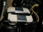
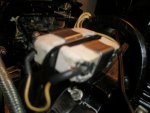
P6021396.jpgP6021399.jpg I do appreciate your kind assistance with my problem. I traced the white wire and two brown wires taped bundle to another taped bundle of more wires that lead to who knows where. It does appear that a white wire does at some point leave the bundle and is attached to this device in the attached photos. Is this device some sort of resistance device designed in the stone age? What is it and could it be the location I am looking for? Since the white wire coming from positive side of the coil leads to another big bundle of black taped wires it might be a nightmare to try to find its origin unless this device is what I am looking for.
 

Don S

Honorary Moderator Emeritus
Joined
Aug 31, 2004
Messages
62,321
Re: Ballast resistor and coil confusion

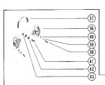
Those are ballast resistors and were used on the 64-72 120's
Item 36 of this parts page.

Ballast resistors.jpg
 

Bondo

Moderator
Staff member
Joined
Apr 17, 2002
Messages
70,526
Re: Ballast resistor and coil confusion

View attachment 150059View attachment 150060 I do appreciate your kind assistance with my problem. I traced the white wire and two brown wires taped bundle to another taped bundle of more wires that lead to who knows where. It does appear that a white wire does at some point leave the bundle and is attached to this device in the attached photos. Is this device some sort of resistance device designed in the stone age? What is it and could it be the location I am looking for? Since the white wire coming from positive side of the coil leads to another big bundle of black taped wires it might be a nightmare to try to find its origin unless this device is what I am looking for.

Ayuh,... I'll venture a Guess that the brown/ white wires nearest, right side are 12V, 'n the 2 white wires, right side, back are a lower voltage...

Meter 'em to know, then hook yer wire to the 12v leg...
 

redgoat

Petty Officer 2nd Class
Joined
May 23, 2010
Messages
102
Re: Ballast resistor and coil confusion

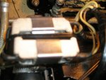
P6031403.jpgP6031401.jpg Now I know why it's taken me a year since I bought this conversion kit to finally get around to installing it. I knew there would be problems--especially since my boat is a 1967--45 years old!
OK with these new photos I am looking straight towards the stern of the boat. The left side of this ceramic piece, i.e. ballast resistor, has a single dirty white jumper wire that is connected to both parts. On the right side REAR there are two dirty white wires attached to the single rear terminal. Also on the right side FRONT there is a dirty white wire and a light brown wire both attached to the single front terminal. Which wires do I test AND how do I test. I have a multimeter with DCV indications on it and two probes--one red and one black. Do I have the boat's ignition set in the RUN position when testing? What should the readings be? Which terminal on this ceramic block will likely be the one I connect the red wire from the ignitor? I know this is a lot of questions but I think I'm getting close on this one.
 

Don S

Honorary Moderator Emeritus
Joined
Aug 31, 2004
Messages
62,321
Re: Ballast resistor and coil confusion

Did you look at the wiring diagram I posted just above your reply?
 

stonyloam

Vice Admiral
Joined
Mar 13, 2009
Messages
5,827
Re: Ballast resistor and coil confusion

In case you are having a little trouble with it: With the switch on, measure the voltage where the two white wires attach to the block. If it reads the same as the battery (according to the diagram it should), that is where you attach the red wire. With the switch on, measure the voltage where the white and tan wires attach to the block, it should read a voltage that is less than the battery. The tan wire comes from the starter and bypasses the resistor only when the starter is turning. The voltage should read 0 with the switch off. Getting closer here;).
 

redgoat

Petty Officer 2nd Class
Joined
May 23, 2010
Messages
102
Re: Ballast resistor and coil confusion

With the ignition switch on and my tester turned to DCV, I touched the rear right two dirty white wires' terminal with my testor's red probe and the black probe to a ground and get a reading of 11.2. I did the same for the front right wires (tan and white) and get the same reading of 11.2 You mentioned a voltage being the same as the battery. I took my testor directly to the marine battery and got a reading of 12.5.
I know I am not doing something right because I am not a mechanic--just a retired teacher. If you could just tell me exactly where to put the testor probes (both red and black) for each test, I should be able to get the results you indicated. I think at this point there are only TWO choices for the correct connection of that d@*# red ignitor wire, namely the front or rear of the right side of the ballast resistor block.
 

stonyloam

Vice Admiral
Joined
Mar 13, 2009
Messages
5,827
Re: Ballast resistor and coil confusion

You might have done this already, but try again, switch on, touch the red probe to the block terminal with the two white wires together, and the black lead to ground, note voltage. Then without moving the ground touch the red terminal to the other block terminal with the white & tan wires, note voltage. Now look under the dash at the back of the ignition switch for a white wire on the back of the switch, red probe on switch terminal (I), black probe on ground note voltage. Measure battery voltage red +, black -, note voltage. ONE of those points should read the same as the battery.
 

redgoat

Petty Officer 2nd Class
Joined
May 23, 2010
Messages
102
Re: Ballast resistor and coil confusion

I did your suggestions and retested. With the ignition switch on, I touched the red probe on the voltmeter to the two white wires on the rear right terminal of the resistor block and the black probe to ground. Result: 11.2. Did the same thing to tan and white wires on right front of resistor block with red probe and black probe to ground. Result: 11.2 same as other terminal. Retested battery at actual battery and got 12.6 volts. My ignition switch is located along a lower side of the boat near the throttle handle and not on the dash. Can't imagine running a wire from the distributor all the way to the front of the boat just to get 12.6volts. Really getting discouraged at this point and fear I might just have to remove the electronic ignition and replace it with my old points and condenser. I have been fretting with this job off and on for two days now. With over 200 hits on this thread surely someone has replaced their points ignition with one of these Sierra electronic ignitions.
 

achris

More fish than mountain goat
Joined
May 19, 2004
Messages
27,468
Re: Ballast resistor and coil confusion

If the points are open (or not connected) when you tested, then yes, you'll get the same voltage both sides of the ballast resistors. The easiest way to see which is the ignition side is to disconnect one side or the other, and then check the voltage. The one with power on it will be the ignition key side....

Chris.......
 
Status
Not open for further replies.
Top