Troubleshooting trim sender/gauge?

Status
Not open for further replies.

nola mike

Vice Admiral
Joined
Apr 22, 2009
Messages
5,072
can anyone tell me how the sender for the trim position sensor works? mine isn't accurate suddenly, and won't hit the bottom of the gauge even with the sensor adjusted all the way.
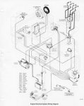
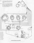
1. i would guess that the sensor is just a rheostat, but looking at the wiring diagrams, it appears that one sensor wire is grounded, and the other appears to go to...the oil temp gauge? (see diagrams). with the ignition on, it seems that there is power to the sensor. i'm missing something. are there testing parameters (ie, in trailer position there should be a reading of x volts/ohms, and at full in it should be y)?
2. my battery gauge is also suddenly reading low by 1-2 volts. i'm guessing these probs are related; i'll check main power and ground wires this weekend, but i'd like to know how the TPS works as well.
3. my "trim up" control also doesn't work, trailer does. i assumed that it had to do with my trim limit switch, but again, i'm not sure how it works--looks like a simple on/off switch? at below trim limit, looks like pressing the button connects blue/wht wire to 12v?

these wiring diagrams are tough to read--are there any "true" wiring diagrams available (eg, that show whether something is acting as a switch/resistor/etc, instead of just showing wires ending at a picture of the component)?
 

Attachments

  • trim1.jpg
    trim1.jpg
    10.5 KB · Views: 48
  • trim2.jpg
    trim2.jpg
    11.7 KB · Views: 41

stonyloam

Vice Admiral
Joined
Mar 13, 2009
Messages
5,827
Re: Troubleshooting trim sender/gauge?

Your trim position sensor (if original) is a wire wound resistor and a wiper arm (rheostat) and the gauge is a voltmeter reading the voltage drop across the resistor. A "new style" one works the same way, except the resistor material is deposited on a plastic sheet, and the contact moves across that. You may be able to disassemble the old style one and clean it to get it working correctly. The new style ones are not serviceable. Mine had a broken wire and read fine till it hit the broken spot then dropped to zero.

As I recall, the trim limit switch is a contact arm that is held in a fixed position by the bellhousing pivot pin. A short strip of copper in the switch housing moves in relation to the tilt of the outdrive (bellhousing). As long as the copper strip is in contact with the arm the tilt up will operate. When You hit "tilt up" the strip moves past the arm till it gets to the end and contact is broken, and the tilt will stop. The trailer button bypasses the limit switch. I think I got that right:confused:
 

stonyloam

Vice Admiral
Joined
Mar 13, 2009
Messages
5,827
Re: Troubleshooting trim sender/gauge?

As to you specific problems: If you take the cover off of the limit switch (be careful) and place a jumper wire between the two screws your limit switch (on the control lever) should work. If it does you have a problem with the switch itself. If it does not you have a problem with the wiring somewhere.
 

stonyloam

Vice Admiral
Joined
Mar 13, 2009
Messages
5,827
Re: Troubleshooting trim sender/gauge?

With you position sensor, I will have to take a guess, since I am not sure if all he way down is min or max ohms :confused:. If down is min, it means that you probably have some small amount of resistance in the system, so the voltage will float at that level and never get down to "zero". Dirty contact or corroded wire connection could cause that problem. Good luck.:D
 

nola mike

Vice Admiral
Joined
Apr 22, 2009
Messages
5,072
Re: Troubleshooting trim sender/gauge?

thanks terry, that's what i thought. given the prob with the volt meter, i certainly have a bad connection at the ground or 12v to the instrument cluster. i'm guessing that zero resistance = "trim down" on the gauge--so a bad connection to ground from the gauge would show the trim as being up. if zero resistance = "trim up", then a bad 12v source would be the culprit. that should be easy enough to determine by measuring the resistance between the TPS wires with the engine up/down. i wonder if all my gauges are off...i guess temp should still be ok, but i wonder if tach/fuel would be affected?

as for the TLS, instead of jumping the switch, looks like there should be continuity with the drive down either between the wires of the TLS or between the pur/wht and blu/wht wires at the control.

i'll check it out tomorrow and keep you posted, thanks for the help!
 

stonyloam

Vice Admiral
Joined
Mar 13, 2009
Messages
5,827
Re: Troubleshooting trim sender/gauge?

as for the TLS, instead of jumping the switch, looks like there should be continuity with the drive down either between the wires of the TLS or between the pur/wht and blu/wht wires at the control.

That sounds right, should read 0 ohms with drive down, if it does, hit the "trailer" switch to bring it up and at some point the contact will be broken.
 

nola mike

Vice Admiral
Joined
Apr 22, 2009
Messages
5,072
Re: Troubleshooting trim sender/gauge?

yup, all the above info is correct. my TPS consisted of a wound wire rheostat, which wasn't making a good connection at one end--the resistance was 30 ohms at the "trim down" position, instead of <5. cleaning the sender fixed that problem. the other gauges were a separate issue, and were solved by cleaning some power leads at the gauges. lastly, TLS problem was due to one of the wires broken within the insulation just before the switch. while it isn't supposed to be repairable, i'm going to give it a shot with either a butt connector, or if i can get enough slack, i'm going to pull the remaining wire through and reconnect it to the switch.
 

stonyloam

Vice Admiral
Joined
Mar 13, 2009
Messages
5,827
Re: Troubleshooting trim sender/gauge?

That is great!:D If you can make the splice, "liquid tape" makes a pretty good flexible waterproof coating. Use plenty, I like to build up 3 or 4 coats.
 
Status
Not open for further replies.
Top