Trim Pump not getting power

Jeklund

Seaman Apprentice
Joined
May 25, 2017
Messages
35
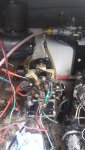
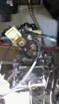
I'm in the final stages of getting my new to me boat up and running and I'm now working on the trim which is the last thing I need before I can get back on the water. I just finished replacing the trim pucks which was a job and a half. I've got the sender hooked up and providing accurate readings. My only issue is when I hit any of the trim buttons nothing happens. I hear no clicking or anything coming from the unit. I was able to test the fuses and the pump is getting power on both sides of the fuses. The boat has been pretty well gutted but the wiring is still intact and just needs to be tied up, I feel there is a decent chance something just got unhooked but even after looking at the diagrams nothing seems off.

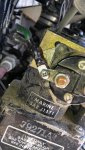
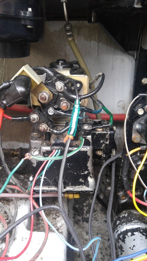
I'm not too sure what to test next the purple line from the throttle gets voltage when one of the buttons are (It's slipped my mind what one) pressed, however, the blue wire that plugs into the limit switch and y splits off does not when any of the buttons are pressed. I'm thinking it might be a ground somewhere that isn't attached but everything looks fine and nothing seems to be out of place. The trim unit is on a Mercruiser 165 unit and is a dual solenoid model. I do know the reservoir needs to be topped off but I feel I would hear some sort of noise out of the unit regardless.
 

Bt Doctur

Supreme Mariner
Joined
Aug 29, 2004
Messages
19,111
on the pumps metal frame is a neg cable connection , the pos connection goes to a buss bar connecting the 2 solenoids shorting the 2 large lugs on a solenoid must make the motor run .
 

Jeklund

Seaman Apprentice
Joined
May 25, 2017
Messages
35
No Title

Alright, I was able to jump those wires and both the up and down functions work. I was able to add fluid and bleed the system so that part is fine now. I suppose my issue lies with the connection from the throttle controls to the solenoids. The wiring seems to be a mess, wires were cut by a previous owner or something.

I've attached a picture of the rat's nest of wiring. The trim limit switch is hooked up to the two plugs (my understanding it doesn't make a difference what one is where but I have tried both), one potential issue would be the green wire that has been cut. It was like this when I got it and I remember it working at one point so I left it. I did attempt to hook it up to the harness plug but that didn't change anything. Where should I start working my way back and testing to figure out what isn't hooked up correctly?
 

Attachments

  • photo268610.jpg
    photo268610.jpg
    161.4 KB · Views: 0

Bt Doctur

Supreme Mariner
Joined
Aug 29, 2004
Messages
19,111
I dont see the second solenoid, I see one solenoid for the up circuit(blue motor wire) the green wire should be connected to the green motor wire for the down circuit
 

Bt Doctur

Supreme Mariner
Joined
Aug 29, 2004
Messages
19,111
UntitledGR_zpsgjwoy95i.jpg
 

Jeklund

Seaman Apprentice
Joined
May 25, 2017
Messages
35
I dont see the second solenoid, I see one solenoid for the up circuit(blue motor wire) the green wire should be connected to the green motor wire for the down circuit

I was thinking that the thing the green wire is connected on the side was the second solenoid. I'll try again connecting that green wire and see what happens.
 

Bt Doctur

Supreme Mariner
Joined
Aug 29, 2004
Messages
19,111
You have 1 solenoid for the up circuit The blue motor wire. The green motor wire goes to a plastic block and get the green wire from the harness.NOT THE GREEN WIRE FROM THE PLUG END that end gets connected to the green wire in the harness. Power for the control comes from the Red wire thru a 20A fuse, thru the plug and into the harness plug to the dash switches . power to the blue wire energizes solenoid that powers the blue motor wire to go up. Going down requires less current so the green wire gets connected directly to the green motor wire.
That other rectangle item is a resetting circuit breaker that is not there normally
 

Jeklund

Seaman Apprentice
Joined
May 25, 2017
Messages
35
Alright so I got that green wire hooked back up into the harness. I tested the buttons on the throttle and they give voltage to the green and blue wire when the appropriate button is pressed. So the issue lies somewhere after the harness connector, correct?

I don't see any wires that look corroded or anything on the pump. Could the limit switch be an issue? I just installed a new one and haven't done anything with it besides plug it in.
 
Last edited:

Jeklund

Seaman Apprentice
Joined
May 25, 2017
Messages
35
No Title

Pictures are attached to the pump with the red wires removed.

I had a slight mistake today that could turn up being a pretty big one depending on how much got damaged. When I was taking those wires off I thought the battery was disconnected but it wasn't. Something shorted out and ended up completely melting the insulation off the shift interrupt switch ground wire. I'm not too sure on the extent of things damaged right now but I've pulled almost the entire harness and starting looking into it. Nothing besides that wire seems fried thus far. What I think happened was one of the power wires on the pump hit a ground and it took the path to the closest ground which ended up being the shift interrupt switch. The best case is that just that one wire is messed up and I'll be able to replace it tomorrow night. Worst case is something component wise got fried and I'll have a whole host of troubleshooting to get into.

It's pretty defeating at this point as I was so close to finishing up everything to get out but I suppose it's just another lesson learned. I'll have to get right back to it as soon as I can to figure out if anything else is messed up.
 

Attachments

  • photo268768.jpg
    photo268768.jpg
    146.2 KB · Views: 0
  • photo268769.jpg
    photo268769.jpg
    114.4 KB · Views: 0

Bt Doctur

Supreme Mariner
Joined
Aug 29, 2004
Messages
19,111
image_268768_zpsppayj0cj.jpg
Red arrow- 12v
remove all yellow block and green arrows, Blue arrow is where the green motor wire goes, it should be a plastic block held by 1 screw tot he housing and th eother screw is isolated and thats where the motor wire goes.
Were doing this step by step
 

Bt Doctur

Supreme Mariner
Joined
Aug 29, 2004
Messages
19,111
The shift interupt has 2 wires .one goes to the coil and one goes straight to ground thru the screw. no other ground path is there?
 

Jeklund

Seaman Apprentice
Joined
May 25, 2017
Messages
35
The shift interupt has 2 wires .one goes to the coil and one goes straight to ground thru the screw. no other ground path is there?

I'll post a picture of the wire that got fried tonight. I just assumed it was a ground because it comes out of the harness to a splice in the harness which has what looks like a bunch of other grounds. It had 3 wires, 2 grey connected together and one black which is the one that went (although it could have been another color prior to melting..).
 

Jeklund

Seaman Apprentice
Joined
May 25, 2017
Messages
35
I'll do my best to get back in tonight after work get those wires off.
 

Jeklund

Seaman Apprentice
Joined
May 25, 2017
Messages
35
As it stands I have everything wired to the best of knowledge and it looks the same as the diagram from what I can see. Picture attached.

20170628_204459_zpsfvgrlwc8_1.jpg


Now I can't get the trim to work every via connecting the two lugs. Is it possible I fried the solenoid and that's causing the issue? Whenever I try to connect power to either the blue or green motor wires it sparks but nothing happens besides the pump jumping a little bit. The green wire from the trim switch is temporarily connected like that until I get everything sorted.
 

Bt Doctur

Supreme Mariner
Joined
Aug 29, 2004
Messages
19,111
Top small lug of solenoid goes to ground, the 3 wires might be motor black wire, trim bullet connector, and that black wire to the left goes to ground.
Large solenoid connections are good

The square block at 8:00 gets removed and the Red wire to the left goes to the small post on the square white block
The green to motor green is ok like that for testing
Applying power to the green or blue motor wire must operate the motor
Applying power to the small blue wire should operate the solenoid and the motor
 

Jeklund

Seaman Apprentice
Joined
May 25, 2017
Messages
35
The square block at 8:00 gets removed and the Red wire to the left goes to the small post on the square white block
The green to motor green is ok like that for testing
Applying power to the green or blue motor wire must operate the motor
Applying power to the small blue wire should operate the solenoid and the motor

Is the small post on the white block on the back or am I meant to move the main power? (Both the power from the battery and to the trim switch are on the white block)

I'm just a little confused as to where the buttons will get power if I remove that block. Also when I apply power directly to the motor wires I don't get anything besides a big spark that seems like its shorting.

Sorry for being such a pain I don't know why I can't get this figured out. If I can't get it going this weekend I may just take it to a shop and be done with it.
 

stonyloam

Vice Admiral
Joined
Mar 13, 2009
Messages
5,827
Got kinda lost going through this thread so I may have missed something, but the simplest explanation here is that the trim limit switch is not adjusted correctly. Run the trim all the way down. Take your voltmeter on ohms and test for continuity between the two black wires coming from the trim limit. No continuity means the switch is not adjusted correctly.
 

Jeklund

Seaman Apprentice
Joined
May 25, 2017
Messages
35
Got kinda lost going through this thread so I may have missed something, but the simplest explanation here is that the trim limit switch is not adjusted correctly. Run the trim all the way down. Take your voltmeter on ohms and test for continuity between the two black wires coming from the trim limit. No continuity means the switch is not adjusted correctly.

I will check this first thing tonight. I ended up replacing the limit and sender a prior to getting into why the buttons don't work.
 
Top