simple Alpha one gen 2 drive install question

CJK440

Seaman
Joined
Nov 29, 2015
Messages
51
I did a gimbal bearing and bellows recently on a 96 Alpha One gen 2. First time wrenching on something without 4 wheels. Installing the drive with a new paper gasket and round rubber seal in the bellhousing. I got the drive installed, shift shaft and lever aligned but there was a small gap between the drive and the bell before the nuts were run down. I couldn't seat it any further by hand. Maybe a 1/16 of an inch.

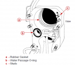
I'm assuming this is the new round rubber seal that is waiting to be compressed (between the U-joing bellows internal lock ring and the front of the drive shaft housing extension) by torquing down the 6 drive nuts.

amigright?
 

Bt Doctur

Supreme Mariner
Joined
Aug 29, 2004
Messages
19,111
If the gimbal bearing was not fully seated in the bore, that would account for a gap, what did you use to install it?
 

CJK440

Seaman
Joined
Nov 29, 2015
Messages
51
If the gimbal bearing was not fully seated in the bore, that would account for a gap, what did you use to install it?

I used an install tool mounted on an alignment tool and a mallet. It felt fully seated when I reached inside and tried to feel it against the step in the transom housing.
 

CJK440

Seaman
Joined
Nov 29, 2015
Messages
51
No Title

How does this seal work (a in the pic). Does it butt against the bellows lock ring and the front of the drive unit pilot or does the drive unit pilot enter the ID? In my haste I did not grease the OD of the drive unit pilot and can see how a dry rubber/metal fit could cause some resistance. I'll remove the drive tonight, grease up the pilot and try again. I have a feeling this is my issue.
 

Attachments

  • photo245062.PNG
    photo245062.PNG
    35.9 KB · Views: 2

Rick Stephens

Admiral
Joined
Aug 13, 2013
Messages
6,118
That big 'square o-ring' should be glued in tight against the ledge using bellows cement. In 2 or 3 dozen drive installs have never felt that o-ring during install.

More likely is if you greased the two o-rings on the input shaft. Too much grease under the o-ring will keep it from compressing into the groove as it gets pushed into the gimbal bearing. Look at them carefully when you pull the drive back off, I've seen them shaved and pieces pinched off.

Double check your gimbal being seated.

Use a wire brush and clean out the splines on the end of the input shaft. I had one that was really hard to slide in and brushing the splines perfectly clean on shaft and coupler solved the problem.

I put a light coat of 2-4-C grease on everything that is bare steel or stainless steel before installation. Entire drive shaft, CV joint, mounting studs. I don't grease it until after I have the two o-rings installed on the input shaft so I don't get grease under the o-rings in their groves.

Rick.
 

CJK440

Seaman
Joined
Nov 29, 2015
Messages
51
I used a tape measure to see if the input is bottoming on the bearing and from the bell face to the bearing inner face is a hair over 8.25". The input when held straight is 8" to the U joint shoulder. So its not interfering. My shaft splines are clean since I replaced the U-joints and used a wire wheel to clean them.

Here's what I didn't do. I didn't grease the driveshaft housing pilot or the input shaft except for the splines. I didn't glue the square O ring either.

I pulled the drive and it came apart easily, the square O ring where it should be. I glued the ring already and will grease the rest of the drive and install it again. I can't rule out cruddy coupler splines but not sure what to do about them.
 

CJK440

Seaman
Joined
Nov 29, 2015
Messages
51
Got it back together all lubed up with the square O-ring glued. Same thing, a small gap between gasket surfaces. I decided to run the nuts down to see what happened. With super low torque (palming the head of a 3/8 ratchet) the gap disappeared.

After looking at it, the big O ring gets pinched between the front of the driveshaft housing pilot and the bellows lock ring. In order to seal there needs to be some sort of interference right? Maybe I just have a tolerance stack of sorts? I'm pretty certain the bellows is locked in the groove and the lock ring appears to be seated all the way.

Another question is my input yoke shaft has 3 O ring grooves. 2 sit inside the gimbal bearing race and I assume act like dampers. The third is closer to the splines and is a much deeper groove for a thinker O ring. Whats the purpose of this? Perhaps to seal the splines in the coupler in order to not sling grease everywhere??
 

williemon

Cadet
Joined
Apr 13, 2016
Messages
23
Just thknking that the alignment and or the gimbel bearing alignment to the coupler could be off. I had the same thing on an 06 gen 2. I thought alignment was pretty close, but once i spent a few hours aligning it, turni g the engine over in 45 degree in rements and checking alignment, bar finally pushed in and pulled out with only two fingers. Then the drive would slide on and mate right up with no gap by hand. Just a thought.
 

Pete104

Lieutenant
Joined
Apr 30, 2011
Messages
1,439
The first groove on the shaft is for couplers that have snout on them. The greasable type couplers with zirc fittings.
 

Scott06

Vice Admiral
Joined
Apr 20, 2014
Messages
5,669
If the gimbal bearing was seated fully I wouldn't worry about it
 
Top