best way/ suggestions jumping out the Black/yellow wire on the power pack?

JQ1

Cadet
Joined
Jul 26, 2015
Messages
14
Ok....I have no spark on any cylinders. I checked with a timing light and nothing. I checked the timing light on one of my cars and it works. I also swapped out the ignition switch and power pack ( had spares) and nothing. Looking at the CDI troubleshooting guide... it first wants me to pull out the connection to the power pack that has the black/ yellow wires. What is the best way you guys have "jumped it" to check the "stop circuit"?

http://www.cdielectronics.com/wp-content/uploads/2013/02/CDI Troubleshooting Guide - 2012.pdf

2001 johnson 150 2 stroke v6 60 degree. Has worked like a champ 'til last week.

Formally known as jquest
 

FarmallM

Seaman Apprentice
Joined
Dec 2, 2010
Messages
43
I pulled the power pack, disconnected the black/yellow wire connector that's located under the power pack, connected an emergency jumper with alligator clip to the power pack end of the connector (need a way to ground the power pack if the engine starts, otherwise you don't have a mechanism to turn it off), then used a remote starter to turn the engine over.
 

JQ1

Cadet
Joined
Jul 26, 2015
Messages
14
Thank you for the assistance. Turned out to be a faulty kill switch on the dash that was giving me the grief. Even though I had the lanyard on it , it was still grounding.
 

JQ1

Cadet
Joined
Jul 26, 2015
Messages
14
Grrrrr.... I thought I was done with the problem , but it came back with the hard starts. After reading a ton of literature... I removed the 5 pin cable connector ( black/ yellow yellow/red, etc. connection from the power pack and cranked. The engine came right up. I started ohming out the connector and the black/yellow wire is fine. It's open, so no issue there. I did notice that the yellow/red wire is under 12v when connected to the pack and cranking. According to what I've been reading that is bad. My batteries measured 12.5 volts, so they're not undercharged. From reading can I disconnect the yellow/red wire from the starter solenoid and jump out the soleniod? Say using a small charger? I would like to see if I get the 12+ without the wire connected to the starter soleniod to see if the starter solenoid is downloading the voltage coming out of the power pack and not allowing it to fire the plugs. I already swapped out the power pack , so i don't believe I have any issues there. At one point.. I cranked the engine with my meter to the soleniod and one time I got 7 volts and another time I got 8 volts. I also measured the yellow/red wire to ground while it was still connected to the soleniod and not to the power pack and I got like 5 ohms. I know that's a coil and should be low, but I'm thinking that solenoid might be close to shorting out and that's why it's knocking down the voltage.
 

Chris1956

Supreme Mariner
Joined
Mar 25, 2004
Messages
27,148
The wiring diaghram for my '98 Johnny 150HPV6 (60*) motor clearly shows that +12VDC is supplied to the powerpack, when the motor is cranking. I would expect your motor to be wired the same.

The 5 wires on the powerpack connector look to be black/yellow for ign killer; yellow/red for +12VDC during cranking, black/orange for shift interrupt, tan for overheat and white/black for quickstart. Since the motor works with the connector disconnected, I would recommend you check shift interrupt switch and overheat circuits, as each kill part of the ignition.
 

JQ1

Cadet
Joined
Jul 26, 2015
Messages
14
Sorry it took so long to get back, but kids and summer will take up your time. Ok....I pulled out the 5 pin connector and the engine fires up. Every time i put the connector back ,engine dies or shuts off. I checked where all the wires went and pulled/ disconnected them to make sure I had the correct wire and chased it back to the back. I slowly started connecting wires back one at time to see which one was giving me grief. I thought I had found the right wire ( yellow/red) because that was the last one I connected. yellow and red only feeds voltage to the pack to help start, so I disconnected it from the coil and the starter switch pin. I checked the wire to see if it was connected somewhere else to see if I had voltage on it. maybe low voltage was confusing the pack and telling it to shut off. I measured the wire and got 240 dc volts. I'm like WTF!
Bottom line I disconnected the jumper from the connector on the wiring harness and measured 240 coming from the pack. As I investigated I found that the 240 was actually coming from the black/yellow pin on the pack. if I disconnected the wire that was leading into the hardness. The 240 would not be on the red/yellow wire.
Point is .....it appears that I'm getting 240 volts from the pins of the 5 pin connector on the pack. I believe those pins should only be inputs, so i see no reason for voltage to be at any of those pins. If there is any voltage it should only be very low or a couple of volts on each of those pins not 240dc. Basically I believe I have a bad power pack that is leaking high voltage into the 5 pin connector. Does this sound correct? There should be any voltage present at any of those pins without any connector connected to them. ???
 

JQ1

Cadet
Joined
Jul 26, 2015
Messages
14
No Title

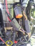
ok... since I can seem to find the edit button. I did some more readings. turns out that both the B/O and B/Y high voltages. So I'm assuming when the laynard is pulled a ground goes through removing the high voltage causing the pack to shut down. Basically your kill switch. So I disconnected the harness plug that goes on the side of the engine under the plastic over. See attached pic. I have the Y/R red basically I isolated. I'm getting an impedence reading sort of like a cap charging, but there shouldn't be anything in that line. The only thing I see is the diode in the harness. I do a diode check and i get like .4. Normally diodes should get about .7 or .6. I know some specialized ones get different readings though. But I'm getting readings both ways. Diodes should only go one way , so i should be getting an open. I'm thinking maybe the diode is going bad. It's not completely shorted, but it's almost there. According to the wiring diagram on my manual....it shows that diode close to the shift interupt switch. Is that a correct representation or is the diode buried in the middle of the wiring harness somewhere? You can see in the pic where I'm checking for impedance. Below is one of the Y/R wires from the coil disconnected.
 

Attachments

  • photo227759.jpg
    photo227759.jpg
    87.8 KB · Views: 1

JQ1

Cadet
Joined
Jul 26, 2015
Messages
14
Diodes checked fine. I have now basically isolated the mws wiring harness on the boat that goes from the instrument panel/steering area to the connections on the engine side. With the cable basically disconnected from both sides....I'm getting some readings on the harness between the y/r and b/y. It's not a dead short, but there are readings . If I put my meter in the diode mode, I get .6 and if I put it on ohms.....I get like 600 ohms and it slowly creeps up. I looked at all the wiring diagrams and images I could find online....that y/r should be open to all the other cables in the harness, but it's not. At this point....I believe the harness if FUBAR'd and I need to order a new hardness. This suxs!
 
Last edited:

Chris1956

Supreme Mariner
Joined
Mar 25, 2004
Messages
27,148
When I bought my '98 Johnny 150HPV6, it came with some partially melted boat harness wires. It worked OK when OI brought it home in Dec 2006, but by boating season, I started to have issues. Specifically, I had a couple of issues with the tach and engine fuse blowing. I found melted wires on the port side of the motor where the boat harness plugs into the motor harness. I also found melted wires under the dashboard, at the trim gauge. I repaired both places, and have not had an incident since (8 years and running). Never did find the cause.
 

JQ1

Cadet
Joined
Jul 26, 2015
Messages
14
I spoke this morning with the manufacturer of my boat. Chalk up another to ethanol. My gas tank sits in the middle of the boat, so they run the lines along the side , through a corrugate tube that is laid out before the floor goes in. This tube also holds all the electrical that goes to the console from the engine. They told me that the ethanol fumes start swelling up the lines and breaking them down. This is because my lines are pre 2006 before they started laying out a fuel line with an extra liner for ethanol. Basically I have to pull everything out and replace it. Oh well.... I'm a glass half full kind of guy. It could of been worse. Electricity flowing, gas fumes. Could of been a big issue. Now I just have a project. Time to bust out the cable lubricant and a come-along.
 
Top