nphilbro
Petty Officer 1st Class
- Joined
- Dec 19, 2011
- Messages
- 304
Narrowing previous thread to single question. Model J175EXEOM
Motor starts well, goes into quick start at +/-1000-1100 rpm then drops to around 700-800 rpms and very smooth.
This was the reading TODAY on my outboard tach, set to 6P.
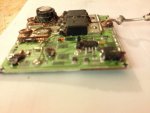
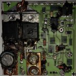
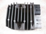
Rectifier is water cooled style and there is no terminal block.
[FONT=arial, helvetica, sans-serif]Good tach reading but non-charging condition seems to be the inverse of everything I've ever read about rectifier issues on these charging systems.[/FONT]
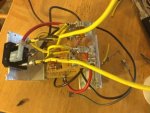
[FONT=arial, helvetica, sans-serif]I hooked the multi-meter red probe between the plug and jacket of the red FUSE+ connection (which terminates with all the red+ wires at the battery side of the starter solenoid), clipped the black test probe to the common case ground bolt shared with other component grounds.
Turn key to "On" voltage drops from 12.7 to 12.63 at the battery. Powered connections now are the AM/FM stereo(standby mode), alarm, and gauges: tach, battery, hour meter.
Start motor: Voltage at the battery drops [/FONT][FONT=arial, helvetica, sans-serif]from 12.7 to 12.3, returns to 12.5 quickly, climbs to 12.57 by the time the quick start routine complete.
Voltage of the purple+ wire from the key switch to key switch ground is the same as the battery terminal voltage. Voltage at the Solenoid+
to case ground same as purple+ to ground regardless of RPM (up to 2k on muffs).
I never get anything over 13+ V at the battery or anywhere in the system with motor running.
*Diode check at rectifier [/FONT]with all wire plugs disconnected from stator, battery, tach and engine not running.(Neither has a gray stripe, gray wire comes directly out of the pack)
[FONT=arial, helvetica, sans-serif]yellow wire "1" reading one direction.
Yellow wire "2" no reading
Another question: are these 35A stators 2 phase or 3 phase? I could run another easy diagnostic test if I knew the answer.[/FONT]
Two batteries on a Pergo 1 Both 2 Off switch. Well maintained, kept on Marine two bank charger (15A max auto switching to 13.7v float). Battery One: 12.7V resting voltage 24 hours off charger, Battery 2: 12.8V resting/24 hours. Batteries are a year old, distilled water added occasionally as needed through the year.


