Charging circuit for Johnson outboard

Status
Not open for further replies.

Sheltering

Cadet
Joined
Oct 31, 2012
Messages
25
I have recently purchased a Bayliner with a 1993 65 hp Johnson outboard. The previous owner had wired up accessories (radio, etc) to a separate battery as he claimed they would drain the primary battery. It seems that the charging circuit is not working. Can someone provide some info on where I begin to check this out? I notice that there are several wires just lying loose in the engine housing that could be related to this problem.
 

boobie

Supreme Mariner
Joined
Nov 5, 2009
Messages
20,826
Re: Charging circuit for Johnson outboard

Post a model #.
 

F_R

Supreme Mariner
Joined
Jul 7, 2006
Messages
28,195
Re: Charging circuit for Johnson outboard

Regardless of the model, attach an accurate voltmeter (multimeter) to the battery terminals, then run the motor awhile. If the voltage increases, the batttery is being charged. No voltage increase, either the battery is not being charged, or something is using the juice as fast as the charging system is producing it.
 

Sheltering

Cadet
Joined
Oct 31, 2012
Messages
25
Re: Charging circuit for Johnson outboard

I notice that there is a four-pin receptacle that is disconnected within the engine housing. Could this be the wiring for the charging circuit? Also, can anyone advise where I could obtain a wiring diagram?
 

Sheltering

Cadet
Joined
Oct 31, 2012
Messages
25
Re: Charging circuit for Johnson outboard

After reading some of the postings, I suspect that I may have a defective rectifier. Can someone advise where to locate the rectifier and is there a way test it?
 

boobie

Supreme Mariner
Joined
Nov 5, 2009
Messages
20,826
Re: Charging circuit for Johnson outboard

Go to cdielectronics.com for test procedures. You could buy a rectifier there or right here on I-Boats.
 

emdsapmgr

Supreme Mariner
Joined
Dec 9, 2005
Messages
11,551
Re: Charging circuit for Johnson outboard

It's pretty easy to identify parts from the factory exploded parts diagrams. Check out: epc.brp.com. A charged battery should read 12.5 or 12.6 volts when charged. Your engine appears to have a rectfier only-the charging is unregulated. Once the engine has run a number of minutes, the battery voltage should gradually increase to 16+ volts. That's normal. If your battery stays at 12.5 after running for 20 minutes, the rectfier is probably not working. The charging circuit is built into the engine's wiring harness and charging will take place through the main battery cables. A 4-pin connector under the cowling might be for the VRO tank. Does your engine have a VRO pump, or the old style premix pump?
 

Sheltering

Cadet
Joined
Oct 31, 2012
Messages
25
Re: Charging circuit for Johnson outboard

Thank you for the responses. I'm quite sure the rectifier is not working as there is no voltage change at the battery with the engine running. I'm not at all sure whether my engine has a VRO pump or not. I know that I mix 2-cycle oil with the gasoline.
 

phillnjack2

Ensign
Joined
Apr 30, 2011
Messages
918
Re: Charging circuit for Johnson outboard

Quote ..A charged battery should read 12.5 or 12.6 volts when charged .

No this is very very wrong at this state of charge the battery is Flat.

The battery should read 14.4 volts before you can call it fully charged, 12.5 -12.6 is a flat battery .

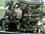
you have a regulator/rectifier combined unit on your engine, its on the same side as the throttle and gear cable linkage.
it will look like the one in the pic below.
thats a rectangle block silver coloured and has fins on it, the size is about 3inch by 1.5 inch (75mmx35mm).
its just to the left of centre in the picture below . this is a 95 engine but same rectifier/regulator.

If your rev counter is working then your charge is probably working as well, if no charge then no rev counter.

by the way your engine year is 1993.
.
14102012(006).jpg


phill
 

Sheltering

Cadet
Joined
Oct 31, 2012
Messages
25
Re: Charging circuit for Johnson outboard

Thank you Phill. Your picture is exactly what I needed - much appreciated.
On the opposite side of the engine there is a four-pin connector (male & female) that is separated. Is it possible that this could be related to the rectifier?

Also, you mention a rev counter. I assume this output is for a tachometer. I do not have a tachometer on my boat, but I do have a speedometer that does not work. Can you comment on the input for the speedometer?
 
Last edited:

phillnjack2

Ensign
Joined
Apr 30, 2011
Messages
918
Re: Charging circuit for Johnson outboard

no the 4 pin connector is only to do with a VRO oil system.
I presume you dont have a seperate oil tank for the engine and that the vro has been disconnected.
you just mix the fuel at 50-1 ratio.

the speedometer is not an electrical thing on these engines.
Most boats having a speedometer use a plastic pipe from the guage to the rear of the boat.
At the very back of the boat (the transom) down at the bottom right or left you might find a plastic fitting
that looks a like something has broken off it, that will be your speedometer.
Sometimes the pipe or the fitting at the back of the boat gets blocked with debris, and sometimes these things get broken
on the trailer.
The fittiting on the back is called a pitot and it just uses water pressure going into it to force air towards the guage.
The same type of thing is fitted to some aeroplanes.
The other type fitted can be a small plastic propellor but these are normally just for slow boats/cruisers.

On your engine control /throttle box just beow the key switch there should be a place to plug in the rev counter.
If not then you might find a grey wire comming out of the loom under the dash, the grey is the pulse for rev counter.

A rev counter is not just for show, it can tell you a lot about your engine and how well its running, and get you better
performance and fuel economy due to the knowledge you gain by using it to get best revs for particular application.

phill
 

Crosbyman

Rear Admiral
Joined
Nov 5, 2006
Messages
4,997
before you go changing the rectifier/regulator.......try confirming that the engine is in fact putting the proper juice (alternating current) from the flywheel (stator/alternator) ​ that needs to regulated/rectified ......and that all connections are shiny and solid in the electrical section

​I do not have any diagram and color codes but I suspect a pair of ...usually yellow wires comes downs from the flywheel with AC voltages ( in the 15-20v range and up to 50 according to CDI)

​please get the proper CDI documentation to confirm.
 
Last edited:

Vic.S

Rear Admiral
Joined
May 4, 2004
Messages
4,699
before you go changing the rectifier/regulator.......try confirming that the engine is in fact putting the proper juice (alternating current) from the flywheel (stator/alternator) ​ that needs to regulated/rectified ......and that all connections are shiny and solid in the electrical section

​I do not have any diagram and color codes but I suspect a pair of ...usually yellow wires comes downs from the flywheel with AC voltages ( in the 15-20v range and up to 50 according to CDI)

​please get the proper CDI documentation to confirm.
You are replying to a 4 year old thread. I expect by now the Op has sorted it
 

Crosbyman

Rear Admiral
Joined
Nov 5, 2006
Messages
4,997
that hurts.....but good point :facepalm: I guess 457F want to help out to :laugh:
 

GA_Boater

Honorary Moderator Emeritus
Joined
May 24, 2011
Messages
49,038
Are you still on here Phil ?

It doesn't matter! This is an ancient thread. Please read the Help Tip on of the page about replying to old threads and start a thread of your own. Thanks.

Closed.
 
Status
Not open for further replies.
Top