


MikeMcGregor
Recruit
- Joined
- Apr 10, 2012
- Messages
- 5
Actually 1968 TRL-10R
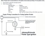
To answer my own question in case others run into this:
The "amplifier" is the rectanlge box "ID'd as electric shift" with leads:
1-Blue to the Coil (same side of the motor to the distributor area) in my case WHITE
1-red lead from power. This lead that comes from battery POSITIVE should be live on run and start - 12vdc!
1-grey lead for the TACH if equiped
1-ground lead (black?).

The BLUE wire that goes to the distributor area should produce a spark when touched to GROUND. If the spark is ONLY to the spark lead from the COIL and not to the plugs then the distributor is the issue. If NO spark then the module (amplifier) is bad. (assuming12vdc + to module and good ground)
The oposite side of the motor has two leads from the points that go to a voltage regulating diode assembly next to the amplifier. This charges the battery during run (I should say "maintains" as it's a tiny output) and provides a path to ground for the points for spark timing. It can be tested with an OHM meter to ground - passes power one way - reverse leads and no continuity.
The amplifier feeds power to the points.... that said - when the points "break" - the amplifier sees this and feeds 200vdc (give or take) to the primary coil which produces the spark. Apparently this is done with and SCR (solid state on-off-switch in simple terms) and a simple transformer contained in the box and perhaps a helping capacitor for power boost (hotter spark). You can test for the signal on the WHITE or BLUE leads with a meter but need to do so with one that will read peak DC voltage - or make a simple diode and capacitor - with a bleed resistor and read voltage across the capcitor to "catch the peak average". Use 400vdc cap small better and maybe a 1K blead resistor and a diode in series (simple DC power supply if you look it up on-line).

I am investigating using a simple 16vac secondary 120 primary transformer and reversing it so see what happens - I suspect the only reason for the SCR is to isolate the "spark-system" from the "Charge-system" ? ? ? May just make one with an SRC - will post how to if it works - $25 beats a $300 Plus part and you can fix it when\if it fails.
Need help. I am VERY mechanically and electrically inclined. Was working fine then starter died - replaced starter brushes - now no spark - I think this has something to do with either the ignition switch or kill switch - there is no Black-with-yellow wire on harness. The ignition switch has been converted to an Automotive switch and has no M -to - M contact. The two leads from the flywheel "pulse" with meter test so I think points are OK. This engine will run with no battery and pull started normally so it has a magneto type ignition?? It has an electronic shifter with a white wire going to the coil primary and the other primary goes direct to ground. From the other side of the flywheel is a dual lead thing that goes to ground on one lead and to the shifter with the other lead. Disconnecting any combination of the leads that lead to the flywheel still give no spark. I can not figure out how the "kill switch" system works on this boat's ignition as nothing I research on-line seems to fit except the principle that KILL is accomplished through "grounding" out the point system but I can not disconnect any leads from the wireharness and get a spark . I have NOT tried applying power through the contact set directly to the white coil primary but this seems the correct power path to follow (eliminating the shifter and boat harness). This white primary reads less than one Ohm as my good meter is dead and can only read on 20 ohm scale digitally with current meter. I firmly feel this has something to do with the kill "12 volt" control system rather than the high voltage or point system ...... HELP - thanks - Mike
To answer my own question in case others run into this:
The "amplifier" is the rectanlge box "ID'd as electric shift" with leads:
1-Blue to the Coil (same side of the motor to the distributor area) in my case WHITE
1-red lead from power. This lead that comes from battery POSITIVE should be live on run and start - 12vdc!
1-grey lead for the TACH if equiped
1-ground lead (black?).
The BLUE wire that goes to the distributor area should produce a spark when touched to GROUND. If the spark is ONLY to the spark lead from the COIL and not to the plugs then the distributor is the issue. If NO spark then the module (amplifier) is bad. (assuming12vdc + to module and good ground)
The oposite side of the motor has two leads from the points that go to a voltage regulating diode assembly next to the amplifier. This charges the battery during run (I should say "maintains" as it's a tiny output) and provides a path to ground for the points for spark timing. It can be tested with an OHM meter to ground - passes power one way - reverse leads and no continuity.
The amplifier feeds power to the points.... that said - when the points "break" - the amplifier sees this and feeds 200vdc (give or take) to the primary coil which produces the spark. Apparently this is done with and SCR (solid state on-off-switch in simple terms) and a simple transformer contained in the box and perhaps a helping capacitor for power boost (hotter spark). You can test for the signal on the WHITE or BLUE leads with a meter but need to do so with one that will read peak DC voltage - or make a simple diode and capacitor - with a bleed resistor and read voltage across the capcitor to "catch the peak average". Use 400vdc cap small better and maybe a 1K blead resistor and a diode in series (simple DC power supply if you look it up on-line).
I am investigating using a simple 16vac secondary 120 primary transformer and reversing it so see what happens - I suspect the only reason for the SCR is to isolate the "spark-system" from the "Charge-system" ? ? ? May just make one with an SRC - will post how to if it works - $25 beats a $300 Plus part and you can fix it when\if it fails.
Need help.
I am VERY mechanically and electrically inclined. Was working fine then starter died - replaced starter brushes - now no spark - I think this has something to do with either the ignition switch or kill switch - there is no Black-with-yellow wire on harness. The ignition switch has been converted to an Automotive switch and has no M -to - M contact. The two leads from the flywheel "pulse" with meter test so I think points are OK. This engine will run with no battery and pull started normally so it has a magneto type ignition?? It has an electronic shifter with a white wire going to the coil primary and the other primary goes direct to ground. From the other side of the flywheel is a dual lead thing that goes to ground on one lead and to the shifter with the other lead. Disconnecting any combination of the leads that lead to the flywheel still give no spark. I can not figure out how the "kill switch" system works on this boat's ignition as nothing I research on-line seems to fit except the principle that KILL is accomplished through "grounding" out the point system but I can not disconnect any leads from the wireharness and get a spark . I have NOT tried applying power through the contact set directly to the white coil primary but this seems the correct power path to follow (eliminating the shifter and boat harness). This white primary reads less than one Ohm as my good meter is dead and can only read on 20 ohm scale digitally with current meter. I firmly feel this has something to do with the kill "12 volt" control system rather than the high voltage or point system ...... HELP - thanks - MikeAttachments
Last edited: