Re: 1972 65 hp Rectifier
YEs it is isolated, until youput the DC ground into the circuit that connects to the battery.
as long as the diodes are in working order no AC will enter the circuit
if the diodes short, the AC sine wave can and will ride on the DC voltage
look at your typical battery charger, the only side rectified is the negative side, the positive side is actually AC stepped down by the transformer and this is used to charge the battery.
take your o-scope and look at the signal, it will be a ac sine wave on the positive side.
this is fine for charging battery, but not good for amp ignitions.
I could hunt the posts but spent over a week helpng someone trouble shoot his ignition system on this forum, he replaced practically everything in the system andstill had intermiottent problems, he finally installed new rectifier and fixed the problem, it had one leg of the negative side of the bridge shorted and alowing AC to go to ground causing all types of weird problems.
In some RF circuits for amplifiers use the same conductors for AC and DC, just use a blocking cap or doorknob cap in series to block the DC and allow AC to pas into the circuit.
FR remember the tube theory, and lighting filiments with AC voltage and the bias and B+ circuits are DC, had to ground the grid with RF chokes and bypass caps to keep the AC from entering?
Same principal applies to the charging system of the outboard.
If that rectifier shorts on the positive side, no worries, it will charge the battery, but make your tach act wierd in display
if it shorts on the negative bridge, then it has a problem because it will go to the ground in the battery and it is connected to the block ground on the engine, as well as the amplifier ground.
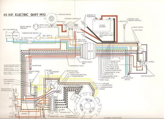
Jay thanks for the schematic.
http://forums.iboats.com/showthread.php?t=235258&highlight=wavrider
refer to this post, wormz had the engine that shows exactly what I am trying to describe,, thaks guys now I got some boots to replace in a mercruiser outdrive


")