1972 electric shift

jim kinser

Petty Officer 3rd Class
Joined
Nov 17, 2007
Messages
94
:confused: I have a 1972 65hp johnson with electric shift . The shift switch in the remote is bad and the least expensive one I can find is $385.00. :eek: Does anyone have a solution for this delima ? Either changing the switch to a toggle on the dash or what. Any help would be greatly appreciated.
 

tashasdaddy

Honorary Moderator Emeritus
Joined
Nov 11, 2005
Messages
51,019

wavrider

Chief Petty Officer
Joined
Nov 26, 2007
Messages
543
Re: 1972 electric shift

Every now and then the controls show up on ebay
 

F_R

Supreme Mariner
Joined
Jul 7, 2006
Messages
28,195
Re: 1972 electric shift

Here's one way. Joe does it differently. I don't reccomend either one. I consider them to be an accident ready to happen.
 

Attachments

  • HydroElectric Toggle Switch.jpg
    HydroElectric Toggle Switch.jpg
    23.1 KB · Views: 5

larky

Petty Officer 1st Class
Joined
Aug 23, 2006
Messages
302
Re: 1972 electric shift

my memory is poor but I thought some one came up with a method using relays or something like that. It was designed to be as safe as the original switch. hopefully someone will know where to locate it if it even exists. I am going to start a search for it now, if I find it I will post the link.
 

Faztbullet

Supreme Mariner
Joined
Mar 2, 2008
Messages
15,616
Re: 1972 electric shift

F_R diagram is correct for hydro electric shifts. easy too
 

jameskb2

Petty Officer 2nd Class
Joined
Jul 26, 2007
Messages
191
Re: 1972 electric shift

Hello All,

I have a similar situation. I plan on a 1971 Johnson 100 horse for my boat, and I wanted to go to a dash mounted switch VS relying on the now outdated and prone to failure control. I will use a simple throttle control for engine speed.

I came up with this idea:

2002400536764198623_rs.jpg


The key switch will not have start, only simple on / off. When on, it will feed power to the fuse block, which will feed power to a three position switch. This is not a simple toggle switch, but a hard throw rotary type found in industrial panels. The forward position will have no power out, (both solenoids are "dead" for forward) the neutral will have power out to the neutral solenoid, AND the "momentary on" starter switch. A push button switch that will serve power to the starter solenoid IN THIS POSITION ONLY. This will force the user of the boat to have the shift switch in neutral to crank the engine. Otherwise, it will not crank. The reverse position will have power out to both the solenoids to shift to reverse. Please note the two diodes in line to provide voltage in one direction only.

I have thoughts of perhaps also making another switch in the throttle control to make sure the throttle is in a low speed position, but I don't think I'll implement it. Yes, there is a possibility of a high engine speed shift change if you don't throttle down, or a chance of the engine being started in neutral with the throttle advanced, but I think common sense will prevail there.

Thoughts, and ideas for improvements are of course welcome!

JK
 

wavrider

Chief Petty Officer
Joined
Nov 26, 2007
Messages
543
Re: 1972 electric shift

The only think I could possible think is if your rectifier shorted then there would be ac on the battery lines and the diodes you have in line would turn in to rectifiers instead of current flow limiters.

Perhaps put a ceramic cap in parrallel with the diodes to ground to take any A/C potential to ground.

Used that same switch alot in heavy industrial manufacturing machinery, good choice as it will not be "accidently" turned.
 

F_R

Supreme Mariner
Joined
Jul 7, 2006
Messages
28,195
Re: 1972 electric shift

Heck, if you want to use a push button start, do this then it will only start in neutral.....
 

Attachments

  • HydroElectric Toggle Switch 3.jpg
    HydroElectric Toggle Switch 3.jpg
    23.3 KB · Views: 6

larky

Petty Officer 1st Class
Joined
Aug 23, 2006
Messages
302
Re: 1972 electric shift

something I would like to see is a "shopping list" of parts needed to build the set-up that jameskb2 has illustrated. i wouldn't know the first thing about what diodes to buy. the list would sure help out many people that have this style of motor(including myself). maybe we could talk iboats into selling it as a kit?


just a thought.
 

jameskb2

Petty Officer 2nd Class
Joined
Jul 26, 2007
Messages
191
Re: 1972 electric shift

Heck, if you want to use a push button start, do this then it will only start in neutral.....

Yep F_R, that would work.

I am using an industrial three position rotary, because you can't just "bump" it and change it's position. You have to grab it and turn it...otherwise it stays where it is. ;) The switch is waaaay over rated for the application, but I want the effect of that F N R like a car, it's intuitive, and will be labeled that way.

I agree Wave, but the factory doesn't have anything like that in the wire diagram I have for the engine. I understand what you're saying, perhaps that voltage cap could be put in the output wire from the rectifier to stop an AC incident. Or, in the input lead to the key switch, which must be on for anything in the starting / shifting circuits to work. :D

Thanks, any input is welcome....I can't think of everything. :(
 

jameskb2

Petty Officer 2nd Class
Joined
Jul 26, 2007
Messages
191
Re: 1972 electric shift

This one has a "buy it now"price of 40 dollars and it should fit yours.
http://cgi.ebay.com/ebaymotors/EVIN...033825658QQcmdZViewItem?hash=item370033825658

Hey Patrick,

I have two of the Johnson style controls here. I just don't want to deal with a dead switch hassle, and since I am completely rebuilding the boat, I decided to do a nice dash panel with all the trimmings. This includes the shift switch and starter button I decided to use. You still can't start the engine without the key, unless you hot wire it of course. :D

I'm playing with the idea of using a foot pedal accelerator like a car too. Spring tensioned to return to low speed if you let off the gas.

But, I don't know if I'll do that. I tend to get carried away with James Bond dreams. :cool:
 

jameskb2

Petty Officer 2nd Class
Joined
Jul 26, 2007
Messages
191
Re: 1972 electric shift

something I would like to see is a "shopping list" of parts needed to build the set-up that jameskb2 has illustrated. i wouldn't know the first thing about what diodes to buy. the list would sure help out many people that have this style of motor(including myself). maybe we could talk iboats into selling it as a kit?


just a thought.

Larkey,

You can buy diodes at any electronic hobby store, Radio Shack is one.

They look like this:

1N5408m.jpg


Diodes are "one way" switches, allowing voltage to pass through them in one direction, but not the other. There is a small voltage drop through them, so a higher volt / amp diode should be used than is required for the application. Say my circuit requires 12v / 10 amps. I would want at least an 18v / 14 amp diode. (70% of capacity used) Most of the time you're going to find 1000v / 1, 3, or 6 amp diodes. I think these will work, according to ohms law. 12v*10amps=120watts. 1000v*3amps=3000watts. However, I am going to make sure of this, asking a buddy of mine that works in electronics.

Diodes conduct current from the anode side to the cathode side. The stripe on the diode is the cathode side. Always "point" the stripe towards the side you want to feed current TO, away from the side you want to keep current FROM.

The diode in the picture is a 1000 volt / 3 amp piece. It's 20 cents to buy it.

Oh and waverider, I could use a Zener type diode if I wanted to cap the voltage with it. 12v rated of course. I just discovered that! :p
 

jay_merrill

Vice Admiral
Joined
Dec 5, 2007
Messages
5,653
Re: 1972 electric shift

Yes, you can install a toggle switch to handle gear selection but I think a full understanding of how the electrical portion of the shift mechanism works on this motor is important. Here is how I understand it.

First, understand the basic function of the electrical portion of the shift system. The 1972 65hp is set up to default to forward gear. This means that, absent electrical current to either of the solenoids in the LU, the motor remains in forward gear. Obviously, this is a handy feature if you have electrical problems away from the dock or launch but there is another reason for it, which I will get to in a minute. When the shift circuitry is receiving 12V DC power and the shift handle is in the neutral position, the Shift Selector Switch sends current to the Neutral Solenoid only. In the same situation, but with the Shift Handle in Reverse, both the neutral and reverse solenoids receive 12V DC power and the LU is shifted into reverse gear.

Next, we must understand where the shift circuitry gets its 12V power from and the answer is from three places - the Battery, the Rectifier Assembly and the Shift Diode & Lead Assembly. Both the Battery and the Rectifier Assembly provide a 12V DC source to the Ignition Switch, through which it is also supplied to the Shift Selector Switch when the key is in the on position. With the system wired this way, the Neutral Solenoid in the LU is energized by the Battery as soon as the Ignition Switch is turned to the on position with the shift lever also in the neutral position. Once then engine is started, the Shift Selector Switch receives DC power from both the Rectifier Assembly and the Shift Diode & Lead Assembly, which are wired into the Shift Selector Switch in parallel.

So why is the system set up this way? Receiving power from the Battery is important because it shifts the LU into neutral before the motor is started. Once it is running, electrical power is provided by both the Rectifier Assembly and the Shift Diode & Lead Assembly and there is sound logic in receiving DC power from two sources when the motor is in a running condition. After startup, the motor will remain in Neutral, or be able to shift into Reverse, because the Rectifier Assembly will provide the "juice" to energize the solenoids. At the same time, excess DC amperage flows to the battery for charging. Once in forward gear, there is no draw (the other reason why defaulting to Forward is advantageous) from the solenoids, and the DC power is directed towards battery charging and running the accessories in the boat. And, not to forget the Shift Diode & Lead Assembly, with this second source of DC power, the LU will remain in Neutral after the Ignition Switch is turned to the off position, because the spinning Flywheel will generate power to send to the Neutral Solenoid. This prevents a surge forward that would otherwise occur between turning off the Ignition Switch and the point at which the motor has stopped turning.

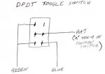
Now that we understand all of that, I think a few things become clear. First, you can not accidentally shift into two gears at once because the electrical system isn't set up in a way that would allow this. Second, I agree that a diode is needed in the home made setup So, absent the issue of the starter cutout circuitry, all we need to do is to bypass the defective Shift Selector Switch by disconnecting all of the shift wires to it, and rerouting them to our replacement switch.

Here are the wires to be concerned with:

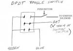
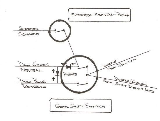
White Wires - these are for the starter cutout circuitry. If luck has it that this portion of the Shift Selector Switch is still working, I would leave the switch in place with these wires intact. May as well let them continue to do their job and be able to use the Start Position on the Ignition Switch. If, however, they don't work, another possibility is to bypass the Start Position on the Ignition Switch and use the switched side of the neutral position on our new shift switch, to feed yet another switch (pushbutton type?). This would energize the Starter Solenoid but it would require the use of another Diode to prevent feedback when Reverse is selected - see diagram.

Purple Wire - this wire supplies 12V DC from the Ignition Switch. It is supplied by the Battery and Rectifier Assembly (red wire to Ignition Switch), via a fused circuit to the battery side of the Starter Solenoid. It is one of the wires that should go to the hot side of the new gear shift switch.

Purple/Green Wire - this wire provides 12V DC from the Shift Diode & Lead Assembly. It is the second wire that should be connected to the hot side of the new gear shift switch.

Dark Green Wire - this is the wire that provides 12V DC to the Neutral Solenoid. It should be connected to both the switched side of the neutral position, and the switched side of the reverse position, on the new gear shift switch. A diode would be needed here to prevent power from feeding back to the Reverse Solenoid when Neutral is selected.

Dark Blue Wire - this is the wire that provides 12V DC to the Reverse Solenoid. It should be connected only to the switched side of the reverse position on the new gear shift switch.

Here's what I would envision in the form of a schematic to accomplish all of this:

NewShiftSwitch.jpg


So, what are the problems in this installation? The biggest one that I see is the one that Joe Reeves mentioned in his post - extreme caution would need to be taken to prevent unwanted shifts with power on the motor. His idea of a guarded switch would help in that regard. There is one problem with this approach, however, in that use of a guard would make switching the LU to neutral cumbersome. Obviously, this could have some negative consequences when operating near a dock or other boats. I do like Jameskb2's approach because it might eliminate that problem.

All in all, I guess I would make the home made switch if I had to but I would sure get on a hunt via the auction sites, Craigslist, etc. to find a used control unit first. I found one for my boat on EBay some time ago and have kept it to canabalize as needed to keep my unit functioning. I don't remember what I paid for it but I want to say that it was about 80 bucks with shipping.


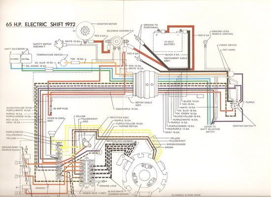
PS: Just in case anyone is interested, here is the OEM wiring schematic for a 1972 Johnson 65hp motor. To make it more legible, save the image to your disk and load it into a photo manipulation program or Windows Picture and Fax Viewer - it can be enlarged in either of these.

1972J65hpWiringSchematic.jpg
 

jameskb2

Petty Officer 2nd Class
Joined
Jul 26, 2007
Messages
191
Re: 1972 electric shift

Thanks Jay!

That's good info. I didn't think about the shift diode circuit supplying energy via the charging system to keep the unit in or out of gear until the engine was stopped. Makes sense. I planned on a "key off" system as I am replacing the power pack (which is insanely expensive!) with an MSD system. I'm going to use a 5200 box for the CDI replacement. It's a point triggered unit, and can be had for a third less than the OEM.

So, when I key off at the switch, it'll kill the engine. I suppose that 2 or 4 second engine momentum shifted into foward (no power to the LU solenoids) could cause a travel hazard.

You're right (you know that!) there IS a starter saftey switch on my engine too. It's activated by the timing advance plate. Hmmm....that eliminates the possibility of starting the engine with the throttle advanced. Nice!

I am trying to do this safe, but different. Like I said, I have two of the proper controls here.

Thanks for your time on that expansive post. When I do this, I plan on documenting everything, with pictures...ect. I'll run it by everyone here again so, as I said, I don't miss something.

I appreciate your efforts!

JamesK
 

jay_merrill

Vice Admiral
Joined
Dec 5, 2007
Messages
5,653
Re: 1972 electric shift

Actually, the shift diode feed isn't via the charging system - it receives AC voltage directly from the Stator and feeds it straight to the Shift Selector Switch. I had to think about this a bit when looking at the diagram, because I kept thinking that doing it this way would deliver 24 volts to the Shift Selector Switch. I kept looking at the purple wire from the Ignition Switch, totally confused, and then realized that, if wired in parallel beside the purple/green from the shift diode, it wouldn't be a 24 volt (12 + 12) feed.

Something else that I am thinking that this setup might do is to minimize forward kick when rope starting an engine with a dead battery. I think you would get a little forward motion but as soon as the flywheel starts moving, the motor should shift to neutral. I'm just not sure how many rpm would be required to get enough juice to the solenids at a level which would accomplish the shift.

I have never tried what I am proposing but I think I have it pretty well thought out. If it works (and it should), I think that the beauty of it is that is keeps just about all of the wiring in a stock condition.

BTW, I replaced both the Powerpack and Timer base in my motor with CDI units. The Powerpack was only 90 bucks. I was engaged in a multi-day SAR here in New Orleans (Lake Ponchartrain) last week and the week before so I ran the motor for long hours with these relatively new parts. All was well and the motor ran like a champ! The only thing that I don't like about the CDI Powerpack is that the cover screws are self tapping and thread themselves into the plastic on the pack. If you get one, don't try to tighten them too much because they are undersized for the pre-drilled holes and strip very easily.
 

jameskb2

Petty Officer 2nd Class
Joined
Jul 26, 2007
Messages
191
Re: 1972 electric shift

Actually, the shift diode feed isn't via the charging system - it receives AC voltage directly from the Stator and feeds it straight to the Shift Selector Switch. I had to think about this a bit when looking at the diagram, because I kept thinking that doing it this way would deliver 24 volts to the Shift Selector Switch. I kept looking at the purple wire from the Ignition Switch, totally confused, and then realized that, if wired in parallel beside the purple/green from the shift diode, it wouldn't be a 24 volt (12 + 12) feed.

I have never tried what I am proposing but I think I have it pretty well thought out. If it works (and it should), I think that the beauty of it is that is keeps just about all of the wiring in a stock condition.

BTW, I replaced both the Powerpack and Timer base in my motor with CDI units. The Powerpack was only 90 bucks. I was engaged in a multi-day SAR here in New Orleans (Lake Ponchartrain) last week and the week before so I ran the motor for long hours with these relatively new parts. All was well and the motor ran like a champ! The only thing that I don't like about the CDI Powerpack is that the cover screws are self tapping and thread themselves into the plastic on the pack. If you get one, don't try to tighten them too much because they are undersized for the pre-drilled holes and strip very easily.

Really? The shift diodes must be the Zener type then and change that AC pulse into the DC clamped at 12v to supply the solenoids. Interesting, and good info again!

Did you change from point triggered to something else? I am simply swapping out the factory power pack to the MSD box. It's the same thing in principal, except the MSD is "multiple spark discharge" and is way cheaper. I don't even know if I can fit it under the engine cowl. I might have to mount it under the splash well or on the inside of the transom. I'd like to see your setup, or the name / parts of it. If it's compact enough to fit in the engine space, I'd go with that. I have a high energy 70:1 coil too, because I've read that you can blow apart the cap and rotor assembly with too much spark voltage. Don't know if that's true, but I decided to stay within OEM spec on the spark voltage. It's epoxy filled, not oil, so it'll handle high vibration.

It's nice to find someone that's done or doing similar things!
 

jay_merrill

Vice Admiral
Joined
Dec 5, 2007
Messages
5,653
Re: 1972 electric shift

The 1972 isn't point triggered - that would be the 1971 60hp. If you have a motor that has 1972, 65hp markings but has points under the flywheel, you probably have an older powerhead on the '72 engine. My engine has a Timer Base, Stator, Powerpack and three Ignition Coils.

The stator provides the AC voltage, which is converted to DC voltage by the Rectifier and Shift Diode. It is a 6 amp system, which, BTW, answers some of the concerns about excess amperage. The basic difference between what the Rectifier and Shift Diode do, as I understand it, is that the Rectifier converts both sides of the AC wave while the Shift Diode is more simple and only uses one side of the AC wave to create DC power. I believe that the Rectifier actually has multiple diodes in it.

In the power pack, voltage from the Stator is fed to the Ignition Coils in the correct sequence via triggers that are switched by impulses from the sensors in the Timer Base. I'm sure there is a much better and technical description but I haven't yet gotten into studying the exact electrical "mechanics" of it all. I like these threads though because, every time I dig into the manual to try to answer a question, I learn a great deal more about my motor. I'm even getting to the point where I can tell my local OMC dealer a thing or two about it, because they don't work on the older motors much anymore and have forgotten things!
 

jameskb2

Petty Officer 2nd Class
Joined
Jul 26, 2007
Messages
191
Re: 1972 electric shift

I see,

Yeah, I guess I assumed that since you had a '72 with electric shift, that you also had a point triggered ignition. Once I looked over your wiring diagram, I seen that you have the multiple coil pulse trigger.

I have a '70 60 horse, and a '71 100 horse. Both are point triggered ignitions with single coil, distributor cap and rotor. After looking at both engine's wiring diagrams (I have the factory service manual for both) I do see that the shift diode power is only hooked to one side of the stator. Yes, the rectifier is a multi-diode unit to handle both sides of the stator. I agree it's simple enough to run that power lead from the harness to the input side of my shift switch. That, coupled with the safety switch at the timing plate to prevent starting in an advanced throttle position will leave shifting while the throttle is advanced as the only safety issue. I don't feel it's a big enough issue to halt my plans there, again common sense and the fact that my switch will be a rotary unit that you will have to intentionally move the position on. It's not going to get bumped and just change positions like a toggle might.

Both charging systems on the engines are the same. 9 amp stators. I can actually swap them out, they have the same part number. I plan on parting out the 60 horse, to help pay for the 100 horse restoration. I sold the cap and rotor already (three cylinder) for $90! I guess they are near impossible to find. Another reason I am going with the V4, the parts are easier to find.
 
Top