1970 johnson 60hp voltage question and more!

thegipper

Petty Officer 1st Class
Joined
Jul 16, 2015
Messages
236
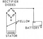
What kind of voltage should the alternator on a 1970 60hp johnson put out? I'm not having any issues but I was just curious? My newer boat battery sits at about 12.5 volts normally, when I start the motor it drops like normal and once the engine is running, the voltage reads about 12.35 volts? Is that normal?

Just want to make sure everything is good.

Also, I've posted awhile ago about my lower unit getting water in it. I fished with it all day sunday and cracked open the drain plug to see if any water comes out. I didn't see any water come out and its hard to tell what the Type C fluid look like after its been used a couple times. It's definitely not "milky" but its not clear like it is in the bottle any more? Also, there is a little hole below the fill plug that seems to leave a small oil spot on my driveway. Is this just oil from the gas/exhaust leaking out that hole?

Thanks for the help guys!
 

F_R

Supreme Mariner
Joined
Jul 7, 2006
Messages
28,195
Battery voltage should increase after running awhile--not decrease. Your symptoms are of an alternator that is not charging. OR, some accessory is turned on that is using more electricity than the alternator can produce (bilge pump?)

Don't worry about the drain hole.
 

thegipper

Petty Officer 1st Class
Joined
Jul 16, 2015
Messages
236
Nothing is on but the motor. I have a separate battery that powers the bilge and livewell pumps. The voltage doesn't drop much, maybe .15 volts (12.5v off, 12.35 running). Is there a spec on how much voltage I should be seeing when it is running?

On every other vehicle/motor I've ever worked on, the voltage always goes up when its running because the alternator is putting out more voltage than what the battery is at rest.

If the alternator is bad, how do you diagnose it? I'm not even sure what to look for.

I should add, when I was testing the voltage, I only had it running for like 10 seconds, not long at all. Does the voltage increase after longer than that unlike on a car when it is instant?

Thanks for any help
 

oldboat1

Fleet Admiral
Joined
Apr 3, 2002
Messages
9,607
I'll guess that the electric gear case requires some power when the motor is running, so there would be a slight drain. That might be what you are seeing. I know there was a long thread about electric shift oil, but I'm not sure what model you have (model number). Charging is from the stator (generates alternating current) through the rectifier, which converts the charge to DC. Your motor may have a clipper circuit which serves as a regulator (and is wildly expensive to replace) -- also a rectifier, which will seem cheap. I'm not sure, but think you may be able to bypass the clipper circuit, if you have it, and operate with an unregulated system. The rectifier is typically the source of charging problems, and can be tested: http://forums.iboats.com/forum/engi...6-small-rectifier-test-by-joe-reeves?t=190638 I can't address clipper circuit testing, but you might do a search for any info on that, or wait for advice here.

Anyway, I think you want the charging system to work.

The lower unit oil might just be a little cloudy from old oil lurking in there with the new stuff you were brow beaten about. One thing you could do is run with it a bit and check it again. Another option is to drain and refill, of course. I don't recall if you had the gear case pressure and vacuum tested (something you could do yourself). A third option would be to drain and reserve the oil, and test the gear case -- then make a decision on the next move.

Hope this helps a little.
 

thegipper

Petty Officer 1st Class
Joined
Jul 16, 2015
Messages
236
Can a rectifier work partially or would one of those other things you mentioned be more likely to "partially work"? I don't think my charging system isn't working at all since I used the boat for about 7 hours on Sunday and the battery was still at 80% according to my battery charger. My motor (60ES70B) ran excellent and started up instantly. The battery seemed to be charged well.

I think at this point, I should test the rectifier. It just seems like the battery should be higher than 12.35v while its running, especially since the voltage is slightly higher when off.

I'm just going to keep monitoring the oil. Maybe the leak is minor and I'll have to change the oil twice a year instead of once?
 

F_R

Supreme Mariner
Joined
Jul 7, 2006
Messages
28,195
The shift does take some current when in neutral or reverse. And the ignition system does take some current also. Nevertheless, the alternator is supposed to supply those, plus more to charge the battery.

Now, you really haven't tested anything with a 10 second run. It takes time for a battery to charge and the voltage to increase. Even so, the voltage while charging needs to be more than while at rest. It is the fact that the voltage is higher that makes the current flow backwards through the battery--that backwards flow is what makes the difference between a charge and discharge condition.

Run it awhile and see what happens. With a fully charged battery to begin with, the running voltage will be around 13 Volts or more. That motor does not have a voltage regulator, so with a long run at speed, the voltage will continue to climb, even to about 16 Volts, which surprises and scares many people. But that is somewhat normal on an unregulated system.

#1 test to diagnose a no-charge system is test the rectifier. They don't go "sort of" bad. however there are four diodes in that thing, and all four diodes must be OK for it to work. That's eight tests to make--one forward and one reverse for each of the four diodes.

You will find some more diodes on that motor also. But the rectifier is almost always the culprit when it doesn't charge.
 

F_R

Supreme Mariner
Joined
Jul 7, 2006
Messages
28,195
Your 1970 may or may not have a clipper circuit. The clipper circuit was a mid-year change and protects the ignition amplifier from voltage spikes. New replacement amplifiers come with instructions saying to remove the clipper circuit, which I really don't understand. Perhaps the new amplifier has built-in voltage spike protection (?)
 

F_R

Supreme Mariner
Joined
Jul 7, 2006
Messages
28,195
No Title

A rectifier. But yours only has two yellow leads, not three
 

Attachments

  • photo61331.jpg
    photo61331.jpg
    25.5 KB · Views: 0
  • photo262563.jpg
    photo262563.jpg
    14.7 KB · Views: 0

thegipper

Petty Officer 1st Class
Joined
Jul 16, 2015
Messages
236
No Title

Ok I think my rectifier may have completely died (or something else)? Boat battery was fully charged before I went out today and eventually the battery lost enough power and couldn't crank the motor over anymore leaving me stranded (very scary situation on Lake Winnebago in Wisconsin). Anyways, I got it back with the help from some people on shore.

I removed the rectifier and found this:

photo263381.jpg attach10380559.jpg

the insulation on the red wire was totally exposed. Plus, the base of the rectifier has a bunch of hairline cracks in it.

On to the test:

Black ohm probe to ground (base of rectifier)
yellow- 000
yellow grey - nothing changes on meter, not even 000
red - 000

Red ohm probe to ground (base of rectifier)
yellow - 001
yellow grey - 588
red - 549

At this point, it seems like the yellow has no reading in either direction, does that mean its bad?

I continued to test per the instructions:

Black ohm probe to red wire on rectifier
Yellow - 549
yellow grey - 533

Red ohm probe to red wire on rectifier
yellow - nothing
yellow grey - nothing

So does this confirm that my rectifier is in fact, no good? Not to mention my battery died and I was only getting 12.3v when it was running a couple weeks ago?

Thoughts? Thanks in advance!
 

F_R

Supreme Mariner
Joined
Jul 7, 2006
Messages
28,195
Are you using a digital meter? Those things irritate me, they are not all alike. Some won't test a diode at all. Some have a dedicated diode test setting. Even a simple continuity test light is a better choice in my book. Nevertheless, from your observations, it would seem the rectifier is shot. In your picture, do I see another bare wire slightly to the right of your rectifier?
 

thegipper

Petty Officer 1st Class
Joined
Jul 16, 2015
Messages
236
FR,

I'll double check but I don't think any of the other wires are exposed. I will go double check with my digital volt meter, I can do a continuity test and report those results too.

Thanks for the quick response buddy! I'm still a little shooken up over this. The wind switched to the east and picked up to about 18 knots. In a matter of 10 minutes we had 4 foot waves and the battery was dead. I was being blown/pushed towards the shore, anchor wasnt holding it was so bad. And of course the trolling motor battery was dead too (or dead enough to not crank it over). It was scary! People on the shore saw us and a guy came out in waders to come bring us in to shore (landing was .5 miles away). we docked my boat at his house, he drove me to the launch to get the trailer and let me drive the trailer through his yard and recover my boat on his shore (over rocks and stuff).

winnebago is a scary lake. Its 30 miles long and like 15 miles wide, if the wind changes like it did, it can be deadly.

Yeah, i was seriously in big trouble.
 

thegipper

Petty Officer 1st Class
Joined
Jul 16, 2015
Messages
236
Ok continuity test with digital meter:

Black probe to ground (base of rectifier)
Yellow - BEEP
Yellow grey - nothing
Red - nothing

Red probe to ground (base of rectifier)
Yellow - BEEP
Yellow grey - 762
Red - 703

Black probe to red wire on rectifier
yellow - 705
Yellow grey - 687

Red probe to red wire on rectifier
Yellow - nothing
Yellow grey - nothing

The fact that I am getting continuity on the yellow wire in both directions in the first two tests, to me, sounds like the rectifier is bad?

THoughts?
 

F_R

Supreme Mariner
Joined
Jul 7, 2006
Messages
28,195
Bottom line:

Should have continuity between one yellow wire and ground in only one direction (must pass both tests).
Should be same result between other yellow and ground in only one direction (must pass both tests).

Should have continuity between one yellow wire and red wire in only one direction (must pass both tests)
Should have continuity between other yellow wire and red wire in only one direction (must pass both tests)

So, you see there are four tests in one direction and four in other direction. It's that easy.
 

thegipper

Petty Officer 1st Class
Joined
Jul 16, 2015
Messages
236
Since I have continuity on the yellow wire and ground in both directions, clearly it fails the test. I ordered a new one, plus the red wire was all messed up.

The motor normally always fire up instantly but I accidentally forgot to put the fuel line back on the gas tank after I filled it. Once I hooked it back up and primed the bulb a bunch, it struggled to start (think it flooded). I was struggling to get it started again a few random times out on the lake, I'm not sure why, it never has done that before. It seemed like it kept flooding (if i would crank it when it was full throttle, it would clear out and run fine). Having to crank it a bunch couldn't have helped with the battery situation. I hope I didn't fry the fuel pump by running it dry?

I'll fix the known bad item first (rectifier) and hopefully everything will be back to normal.

This is a totally different question but it appears the "start/run" little lever doesn't seem to be working. If I pull up on it to the start position, it doesn't idle any higher (seems like its not working). Does anyone know how it works? I only see one cable which is the throttle cable. when I pull up on the lever, the throttle on the motor doesn't move at all. Anyone have any insight on this?

Thanks for help of course!
 
Last edited:

F_R

Supreme Mariner
Joined
Jul 7, 2006
Messages
28,195
Needless to say, the lever should move the cable a bit if you lift it. There may be a lot of slack or slop in the cable or its attachments. You may have to take the box apart to see what the problem is. Be careful with that shift switch in there. It is worth as much as the whole rest of the motor.
 

thegipper

Petty Officer 1st Class
Joined
Jul 16, 2015
Messages
236
If the idle adjustment on the engine (screw on the throttle lever), is adjusted to high, would you not see it move when you lift the start/run lever? I think the motor is idling higher than it should be. I'll check that tonight.
 

F_R

Supreme Mariner
Joined
Jul 7, 2006
Messages
28,195
You should always adjust the motor with the throttle cable disconnected. Then connect the cable and adjust it to the motor. Cable should pull the throttle back against the idle stop when in neutral and warm-up lever down. Always adjust the cable to the motor, never adjust the motor to the cable.
 

thegipper

Petty Officer 1st Class
Joined
Jul 16, 2015
Messages
236
Sounds good, I'll give that a check.

Any thoughts on my starting issues after running it out of gas? Fouled plugs? Fuel pump?

Thanks for the help!
 

oldboat1

Fleet Admiral
Joined
Apr 3, 2002
Messages
9,607
just my two cents: The throttle cable could be the issue for everything you describe (can be adjustment or assembly). Need to troubleshoot like F_R describes.

You should not be able to crank (attempt to start) in gear and at full throttle, but maybe I've missed your point. The neutral safety switch should prevent starting that way.
 

thegipper

Petty Officer 1st Class
Joined
Jul 16, 2015
Messages
236
I'm not sure my controls have a neutral safety switch, I'll have to check the parts diagram.

I checked the parts diagram and I don't see a neutral safety switch. I'm guessing mine doesn't have one because of the electric shift in this motor. With no power to the shift solenoids, the motor is always in forward gear so you can always get home if they fail. That's my guess at least.
 
Top