1964 Johnson 3hp Model JH19A Serial # 101739 Rebuild

helicopterjohn

Seaman Apprentice
Joined
Jul 18, 2012
Messages
40
A friend of mine just gave me a 1964 Johnson JH19A outboard motor. The motor exterior looks really nice for its age. I thought it might be a nice motor to restore.

Overview:

The motor was locked up and the pistons were frozen to the cylinder walls. Tried several applications of PB Blaster over several days and was unable to free it up. I finally got the pistons out but damaged one of the rods (stamped 277168 on the side of the rod). Also, the rings were frozen and broke when they were removed. The cylinder walls honed up nicely and I think the block will be serviceable as well as the crankshaft. This motor has bronze bushings on the crank and rods (no needle bearings).

The carb was corroded badly and was not usable.

I found a used carb on e-bay off of a running Jw18 Johnson 3 HP which from the pictures supplied looked identical to mine. I ordered it and it is on the way. It may require a rebuild kit but I see that they are readily available.

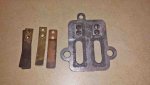
The reed plate was pitted where the reed valves seat on it and is un-usable. I have made necessary cad/cam drawing for it and can easily duplicate it on my CNC machine. The reeds themselves seem to be in good shape.

As I mentioned above I have at least one bad rod and the other is questionable. The pistons seem to be serviceable and would probably accept new rings.

I found a couple of used piston/ring/rod assemblies on e-bay that I think??? will work with my engine. From the pictures supplied I can see part of the casting number (i.e. 277???) can't see the last three numbers but would hope they are stamped 277168 like the ones in my motor. I made an offer of these items and hopefully they will work. Of course the rings may have lost their tension and I may need new ones. In reading other posts on similar 3hp Johnson Outboards here on the forum of this era I understand that the ring set (i.e.2 rings for one piston) are still available under part # 378412. Hopefully, these rings would fit my engine in case they are required.

My hope is that if I can solve the piston/rod/ring issue I should be well on my way to getting the motor to run.

The rest of the motor and associated parts came apart easily. None of the other parts had any signs of corrosion and the motor must have been used in fresh water only. The water pump and impeller are in great shape as well as the lower foot assembly and gear box, prop etc.

If anyone here has any input to verify the part numbers on the rings, rods, and pistons utilized in my JH19A Johnson 3hp 1964 model outboard and possible vendor choices I would appreciate your reply. Any other ideas suggestions would also be appreciated. Also the torque numbers on the rod bolts and head bolts would be appreciated.

Thanks,

John
 

HighTrim

Supreme Mariner
Joined
Jun 21, 2007
Messages
10,486
Connecting Rod Bolt Torque is 60 to 66 INCH LBS
Head Bolt Torque is 60 to 80 INCH LBS

I think making a new intake manifold plate from scratch is unnecessary! Unless you really like doing it. Would not be hard to find another.

I will send you a PM on here regarding parts.
 

helicopterjohn

Seaman Apprentice
Joined
Jul 18, 2012
Messages
40
Hi HighTrim,

Thanks for the torque specifications. They will come in handy during re-assembly.

I received the used carb yesterday and it really looked good with no corrosion. ;) Of course, it needed to be cleaned a little and required a repair kit. I removed all the gaskets, low speed needle etc. and will soak it in carb cleaner to help remove any gum/debris in the internal passages over the years. I also removed the nut on the front of the lower carb bowl and insured that the high speed jet was clean. Ran carb cleaner in both directions and blew it out with air and it seems to have good flow. I didn't use any type of cleaning wires as I didn't want to oversize the metering hole in the jet which could cause flooding. I ordered the kit with new float, needle, seat and associated gaskets etc. yesterday and will have the carb cleaned and ready to install the kit.

During my dis-assembly of the carb I noted that the low speed needle was set at about 3/4 turn out from seated position.
Would this be a good starting point when I attempt to start the engine?

Thanks in advance for your help.

BTW: Is there any way to edit a submitted item in a thread here on the forum in case you needed to add or correct submitted information add pictures etc.? I noticed after posting this item that an edit button appeared in the bottom tool box. My first post in this thread doesn't have it. Are you only allowed to edit the post for a certain amount of time?

;)John;)
 
Last edited:

HighTrim

Supreme Mariner
Joined
Jun 21, 2007
Messages
10,486
Im not computer saavy but I believe you are correct, I have noticed as well sometimes I cannot edit a post for some reason.

For the needle static setting, you usually start them at about 1.25 to 1.5 out from seated and adjust from there, 3/4 may very well be where it ends up though.
 

Chinewalker

Fleet Admiral
Joined
Aug 19, 2001
Messages
8,902
I believe you lose the ability to edit an individual posting once someone replies to it.

Even though you stated your impeller looks good, throw a new one in there while you've got it apart. Go with OEM if you can, as I've had some issues lately with aftermarket Sierra impellers being too thick in the housing. Always had good luck with them in the past, but they seem to be sourcing through cheaper avenues lately, with quality suffering in the process. They're inexpensive either way.
 

helicopterjohn

Seaman Apprentice
Joined
Jul 18, 2012
Messages
40
Hi Chinewalker,

Thanks!
I will take a second look at the impeller once I get it running.

John
 

helicopterjohn

Seaman Apprentice
Joined
Jul 18, 2012
Messages
40
No Title

01-12-17 Update:

Reed Valve Plate:

I performed an inspection on the reed valve plate and found it very pitted and I am sure it would not allow the reed valves to work as designed. See attached Photo.

I have the necessary equipment to make a new plate and have made the CAD/CAM files for cutting the new part. The reeds looked fine and I will clean them up prior to reinstalling on the new reed plate.

Carb. :

I dis-assembled the used Carb. that I purchased on e-bay and cleaned it with carb. cleaning solution and it now looks like new. All of the mechanical items seem to work fine. I removed the float, needle and seat assembly and blew air and carb cleaner through the passages to make sure that everything was clean. I removed the low speed needle valve and blew carb cleaner and air through it to make sure that the needle seat was clean and all passages were open. I also removed the inspection nut on the front of the bottom bowl. I blew carb cleaner through the high speed jet and cleaned it with air blowing both directions. I then inspected the high speed jet but shining a small flashlight into the interior of the bowl and looking in the front end of the bowl where I had removed the inspection nut and I could easily see through the jet and see a nice uniform round hole that was back lit. I ordered a new carb kit that also included a new float. It should be delivered today or tomorrow and then I will install the appropriate supplied replacement parts.
 

Attachments

  • photo257428.jpg
    photo257428.jpg
    82.8 KB · Views: 0

lindy46

Captain
Joined
Nov 27, 2008
Messages
3,886
Clean the old packing material out of the slow speed needle opening. and if you haven't done it, remove the welch plug on top of the carb and clean out the slow speed circuit underneath. Carb kit will have new packing and a new welch plug.
 

oldboat1

Fleet Admiral
Joined
Apr 3, 2002
Messages
9,607
Pictures can be deceiving (even really good ones like you've managed to post!). But the carb doesn't look squeaky clean to me yet. I would unbolt the copper lines and soak tops and bottoms in cleaner (I like lacquer thinner, but your call. Some guys like Pine Sol. Need whatever will cut through old fuel varnish.) Leave the linkages in place, but take off the domed fitting on top like Lindy mentions (soak after taking off the fitting or plug). Finish by spraying carb cleaner through all passages. Remove the low speed needle and make sure the point is intact and unproved -- soak the needle along with all the other metal parts (pull that rubber washer out first, btw). I like to dry fit it while the top is still open to see that it fits properly. Also, use a large bladed driver and carefully unscrew the brass nozzle shown in the pic -- soak that too, and clean out the small holes. When finished, you shouldn't see any bits and pieces of anything or any residue.

Sweet running little motors. Should idle way down low and slow when clean and tuned.
 

helicopterjohn

Seaman Apprentice
Joined
Jul 18, 2012
Messages
40
Update:

Both the cylinder block and cylinder head have been lapped on a surface plate to ensure that the new head gasket makes a good seal. The cylinder walls have been honed to ensure that the rings seat properly.

1964 Johnson JH19A 3hp Cylinder Block Lapped For Mating With Cylinder Head


1964 Johnson JH19A 3hp Cylinder Head Lapped For Mating With Cylinder Block


thatone123

Banned
Joined
Mar 7, 2009
Messages
707
Gee, I just disassembled a 1984 4.5 long shaft and would sell the good engine for cheap. Has good compression. In fact, I still have the whole motor and parts, but the throttle handle is shot and hard to find and expensive and a pain to install so I parted out the engine and may sell some of it on E-bay or keep the parts for my own use down the road. I had a thread here on it and found out the prop shaft is salted into the motor socket. It should pull out after a bout of penetrating oil. Have it soaking now.
 

thatone123

Banned
Joined
Mar 7, 2009
Messages
707
I've cleaned lots of cabs and seldom does the welch plug need removed or replaced in my experience. I live in a cool climate though and no ethanol corn gas here. That is a clean carb! Mine don't look that good even after a day in Berrymans carb cleaner.
 

helicopterjohn

Seaman Apprentice
Joined
Jul 18, 2012
Messages
40
Hi,

Thank you guys for the carb cleaning tips. I haven't removed the packing washers that keep tension on the low speed needle as I haven't received the carb. kit yet and didn't know what pieces would be included. I will remove the welch plug on top of the carb. on the low speed needle when I get the carb kit and clean all the associated fuel passages. I also removed the inspection nut on the front of the bottom bowl. I blew carb cleaner through the high speed jet and cleaned it with air blowing both directions. I then inspected the high speed jet but shining a small flashlight into the interior of the bowl and looking in the front end of the bowl where I had removed the inspection nut and I could easily see through the jet and see a nice uniform round hole that was back lit by the flashlight. After I cleaned the worst of the derbis out of the carb. I soaked it in carb. cleaner and then rinsed it off and blew it dry with air. I will probably give it one more dip in the carb. cleaner after the low speed packing and welch plug are removed just to be sure it as clean as possible. I haven't worked on too many outboards but have done hundreds of lawn mower and weed eater carbs. FYI: The low speed needle taper looked nice and smooth. Any advice you guys can offer will be appreciated.

BTW: Never heard of the Pine Sol cleaning treatment. I will have to grab a bottle and see what the ingredients are. Guess if it is good for floors it probably won't hurt the carb. What is the mix ratio on the Pine Sol solution? A friend of mine that works at a local lawnmower shop uses an ultrasonic cleaner for cleaning carbs and he loves it.

Thanks,

John
 

oldboat1

Fleet Admiral
Joined
Apr 3, 2002
Messages
9,607
Think you're close -- often can't see the stuff that stops you, unfortunately. Doesn't take much. I think HighTrim prescribes PineSol, and he does a lot of them.

On the needle -- meant to suggest you want to check it for grooves (see I had a typo).

Not to be too much of a naysayer, but the head cover looks like it could use a tad more polishing. Some scratches that probably wouldn't affect operation, but worth a little more sanding if it's still apart, imo. I use 400/600 grit, figure eight motion -- probably what you are doing.

Hope you keep posting. Good project.
 

helicopterjohn

Seaman Apprentice
Joined
Jul 18, 2012
Messages
40
Ignition System:

These are some pictures of the unit at tear down. I have some cleaning to do here and will remove and inspect the points, condensers, coils and replace if required.

I wonder what the air gap is on the points and also the coil to flywheel air gap.

Thanks in advance for any information or advice you may have to offer.

1964 Johnson JH19A 3hp Ignition System At Tear Down (Side View)


1964 Johnson JH19A 3hp Ignition System At Tear Down (Top View)


lindy46

Captain
Joined
Nov 27, 2008
Messages
3,886
Wow! Lotta rust under there. Was this a saltwater motor? As long as you've done so much restoration work already, I'd invest in new points, coils and condensers too. What is that "goo" on the cam? BTW, points gap is .020" at the high point on the cam. Coil laminations should line up with the mounting bosses on the mag plate.
 

Chinewalker

Fleet Admiral
Joined
Aug 19, 2001
Messages
8,902
Coils look okay. I'd clean up the lams a bit and leave 'em be. Coils themselves are sealed and magnetic fields don't care about a little surface rust on the lams... Points, yeah, they'll need to be replaced. Condensers, may get by with a good clean-up. They need to make good ground to the mag plate and rust can inhibit that... They're cheap, though, so new may be in order.
 

HighTrim

Supreme Mariner
Joined
Jun 21, 2007
Messages
10,486
Ideally, you want your coils out as far as they will go without hitting the magnets.

So, as Lindy states, use the top of the angle of the mounting boss as a guide. If you run your nail up the flat boss, you should not catch your fingernail on the laminations. If you do, its out too far. You want it just on the edge, in too far, and you limit spark. If you want, and plan on working on more of these, FR on this forum makes a very handy coil locating ring. You drop it over the coils, pull them out till they touch the ring, then tighten down. Sets them with the perfect gap every time!

Check the primary and secondary circuits of the coil as well.

The primary is between the black ground lead, and the green lead that goes to the points. It is a shorter, fat wire and is rarely broken. You should bury the needle testing its resistance. IE read 0 ohms, or continuity.

The secondary is a longer, thinner wire, and is often the problem if the coil is shot. You test it between the spark plug wire, or the pin if you remove the plug wire, and the black ground lead. On these Universal Magnetos, 3500 to 8000 ohms is acceptable, depending on the coil. Your coil shown should have about 6000 to 7000 ohms resistance.

These tests will show an obvious failure, however they will not show a fracture in the primary or secondary windings. What can happen, is you can have a fracture of the wire. However, it will still be touching and will test good. When running the motor, the coil will heat up. As we all know, heat causes expansion. The wires will separate where they are fractured, and you will lost spark. This can be frustrating for someone that does not have proper test equipment, like a Mercotronic, which puts a load on the coil while it test it.

Don't let me scare you though, testing the primary and secondary with a meter will be good enough 9 times out of 10 or better. Just wanted to provide some background on what COULD happen.

For carb cleaning, on the decent looking ones I use Pine Sol which I gradually water down as my dip tank gets low. I start out straight. Just better for the skin, as im bad at wearing my gloves, and my wife prefers the smell of the Pine SOl over carb cleaner on me lol.
 
Top