Evinrude 40973R 40HP - Selectric shift - reverse goes forward!

F_R

Supreme Mariner
Joined
Jul 7, 2006
Messages
28,195
If memory serves me correctly, the 1973 OMC motors 50 hp and up had hydro-electric shift, (lever operated), this is not be confused with "Selectric" push button shift of the late 60's.

On the 73 models, if the "electric" assisted shift stopped working, Legend and Lore has it, you should still be able shift F-N-R, but with more effort.

Are there any shift solinoids on that motor? a parts diagram would tell you., you may have one thats gone bad.

BRP still has all the exploded parts diagrams and (latest) numbers for the motor on their BRP catalog website. I can still get anything I need for my 1973 25 Johnson.

Hope this helps.

With all due respect, 40973 is a 1969 40hp with electro-magnet coils and spring clutches. Let's not mix apples and oranges.
 
Joined
Jul 22, 2016
Messages
52
haha ok, there it is. sorry for the double post.

thanks to the tips here, I am confident this engine has selectric shift, not hydro-electric. Purely electro-mechanical here. That said, as far as nomenclature goes, I do believe any electromagnet is a subset of the solenoid family, so if you get into semantics, yes, this engine has two solenoids. but thats another conversation.
 
Joined
Jul 22, 2016
Messages
52
so it looks like I need to dig deeper. is there a manual anywhere online that outlines disassembly of this unit?
 

F_R

Supreme Mariner
Joined
Jul 7, 2006
Messages
28,195
Steve, the next step you need to take is remove the lower unit from the motor. I'm betting you will find the cable burned up.
 
Joined
Jul 22, 2016
Messages
52
yargh. ok. was hoping to not have to remove the LU on this thing pretty much ever, but Im sure I can figure it out!
 

racerone

Supreme Mariner
Joined
Dec 28, 2013
Messages
36,299
These lower units have electromagnets.-----A solenoid generally has a component that moves.---Not so in this lower unit.----Good luck with the project.
 
Joined
Jul 22, 2016
Messages
52
thanks!

so here's a noobie question for ya. Im not sure exactly what defines the LU proper, more specifically, exactly what i need to take apart. I attached a photo, the "lower portion" of the engine seems to come apart at two points... shown at the red and blue lines. The red line looks easier to take apart, a bunch of bolts and Im off. the blue one doesnt look too much worse, a bunch of bolts, plus I need to disconnect a bunch of flexible engine mounts, and maybe the front half of the engine cover?
 

Attachments

  • evinrude.jpg
    evinrude.jpg
    84.4 KB · Views: 0

interalian

Commander
Joined
Jul 23, 2009
Messages
2,105
Red line. Make sure you get all the bolts. Some may be hidden under trim tab. And make sure to disconnect the wires first, and attach a fish wire so you can thread them back up when you're re-installing.
 
Joined
Jul 22, 2016
Messages
52
woohoo! thanks for the good news Interalian. Looks like I can get that thing off in about a half hour. Then dismantle... and see what ensues! good tip on the fish wire, I always forget to do that till its too late.....

those connectors are kinda funny. not the standard bullet or spade type im used to... theyre kinda semi-permanently fastened to one another...
 

F_R

Supreme Mariner
Joined
Jul 7, 2006
Messages
28,195
Called "knife connectors". Named after a jackknife blade and the way it opens and closes.
 

interalian

Commander
Joined
Jul 23, 2009
Messages
2,105
They're called 'knife connectors'. Pull back the neoprene sleeve, then open them up like you'd close a jacknife.

Edit: missed post 31 at top of next page - d'oh!
 

jimmbo

Supreme Mariner
Joined
May 24, 2004
Messages
12,961
You don't have to worry about any bolts under the trim tab/exhaust snout. There is a bolt covered by the lower rear cover, but if the picture with the red and blues lines is the engine, it is exposed. Good luck!
 

F_R

Supreme Mariner
Joined
Jul 7, 2006
Messages
28,195
No Title

A friendly warning: If you have to go inside the lower unit, the lower, bullet shape part, is held to the part above it by two long studs with nuts. If you remove the nuts and allow the bullet section to fall away, it will rip the coil wires apart. They are not replaceable except to replace the whole coil. And they are stainless steel wire (not solderable). Have the unit laying on it's side before removing those two nuts. Don't ask me how I know.

On the other hand, more often the studs are corroded in so badly that it is dang near impossible to get it apart without a hacksaw. Yep, that's how to do it, a hacksaw applied in the right location, then a welder. Have fun.
 

Attachments

  • photo254189.jpg
    photo254189.jpg
    142.6 KB · Views: 0

racerone

Supreme Mariner
Joined
Dec 28, 2013
Messages
36,299
Those wire connecters are absolutely brilliant.----Positive connection.----The same year after year.------Far better / simpler than the 5000 or so PLASTIC connecters used in the automotive industry where you have to figure out each one.
 

interalian

Commander
Joined
Jul 23, 2009
Messages
2,105
Those wire connecters are absolutely brilliant.----Positive connection.----The same year after year.------Far better / simpler than the 5000 or so PLASTIC connecters used in the automotive industry where you have to figure out each one.

Simpler yes, better :noidea:.

Imagine trying to hook up the hundreds of wires connecting a modern DME on your fuel injected, ABS, DSC, LMNOP car, and sliding neoprene sleeves over each connection, and the space all of that would take. Give me a well engineered multi-pin connector for that any day, especially when several otherwise identical connectors are keyed to prevent mis-mating.
 
Joined
Jul 22, 2016
Messages
52
cool thanks for all the additional tips and info guys! I will tread lightly when dropping the LU and take heed to the advice you've left here. Hopefully I dont break anything and there is minimal hacksaw type work! Depending on where today goes.... I might get around to it...
 
Joined
Jul 22, 2016
Messages
52
you guys will get a kick out of this.... especially considering the recent "wire connector of choice" conversation!

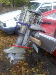
​I took of the lower unit gearcase off the engine, and didnt see any damage to the wires leading to the "bullet shaped" bit. All looked good, so I decided to take off the lowermost bullet part. Heeding F_R's advice, I loosened the two big studs (was easy, minimal corrosion) and carefully separated the bullet from the LU with a screwdriver. I only saw one wire and it had plenty of slack, so I continued to separate. Got it apart, and realized it was another one of those "knife" style connectors. I peeled the rubber back, un-knifed them, and pulled the bullet away from the rest of the LU.... cool, i thought...

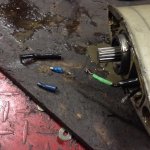
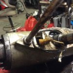
then i realized there's another wire in there! Duh! but I swear, it wasnt me that broke it. Somebody's been in here before! The blue wire has been "repaired" at some point with a classic auto style bullet connector. we all know those have the potential to suck greatly. if some bozo puts them on wrong, they'll come right off the wire when you go to disconnect them. SO its possible I pulled the connectors right off the wire when I separated the bullet part, but I was very careful to peer into the crack between the cases to be careful about the wires. I only ever saw one that was connected. I have to expect the blue one was already disconnected. How/why is the next question.

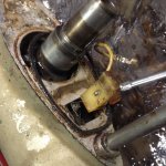
If you look where the wires enter the bullet casing, there's a whitish/yellow piece of plastic, and a piece of metal just below it. Its a little garbled up/out of place if you ask me. I think the blue wire is connected to that, and that might have got sucked into someting/chomped up by a gear somehow?

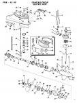
I guess I need to keep dismantling this gearcase entirely, and see what the wire situation is in there. Once I can get at the leads, I can take resistance measurements at the coils proper and see if they are still ok. Hoping they are, in which case I just need to repair the wires that connect to them. F_R mentioned I would not be able to solder anything back on, which may be true, but I'm sure I can come up with a mechanical means with which to fasten the wires back together in a semi-permanent fashion. We shall see.....
 

Attachments

  • IMG_0510.JPG
    IMG_0510.JPG
    65.5 KB · Views: 0
  • IMG_0511.JPG
    IMG_0511.JPG
    106.9 KB · Views: 0
  • IMG_0512.JPG
    IMG_0512.JPG
    102.8 KB · Views: 0
Top