Colours wiring evinrude ocean pro 159

Andrik

Petty Officer 3rd Class
Joined
Sep 21, 2015
Messages
96
Does anyone know where these two cables (with three wires) shall be connected on the dashboard? I know purple is for the ignition switch, but there already is noe in the 6-pin connector to the switch.
 

Attachments

  • photo238846.jpg
    photo238846.jpg
    230.1 KB · Views: 0

bob johnson

Rear Admiral
Joined
Feb 25, 2009
Messages
4,304
there is an extra set of wires up front in case the boat does not have the systems check tach...... so you can hook up ignition power .

bob
 

Andrik

Petty Officer 3rd Class
Joined
Sep 21, 2015
Messages
96
Thanks a lot. I have now wired everything on my engine stand, but I still have no power when turning the switch. No power that comes trough the harness. Could it be because I haven`t connected the two yellow/red wires (engine start I guesss) that comes from the control box? I have not found where to connect them,
 

bob johnson

Rear Admiral
Joined
Feb 25, 2009
Messages
4,304
in recollection...those yellow/black, and yellow/red wire are important in the stop circuit...... so having them unconnected is most likely one reason... not knowing what the control is and what wires are actually connected and what else is not connected...its difficult to trouble shoot your issue...

bob
 

Andrik

Petty Officer 3rd Class
Joined
Sep 21, 2015
Messages
96
No Title

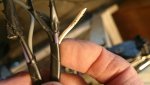
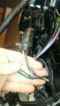
Ok, here`s some more photos. In lack of a Deutsch 6-pin connector, I made a provisional connection;

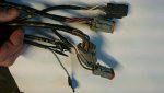
Pin1 Yellow black to M
Pin2 Yellow/red to S
Pin3 Black/white to M
Pin4 Purple to A
Pin5 Purple/red to B
Pin6 Purple/white to C

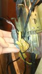
I attached a photo of the twi bullet connectors that come from the control box.

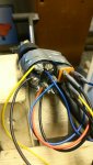
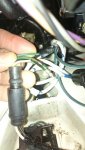
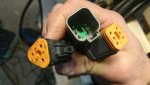
There also is one more connection I do not understand; There is a bullet connector that seems to fit together, the female part is black and comes with the VRO-harness, the male plug is green (trim) and comes with black and white/brown (Trim sender to gauge, I think). Should these be connected??? Please see picture 3 and 4.

I do not know if this gives enough information?
 

Attachments

  • photo238874.jpg
    photo238874.jpg
    228.4 KB · Views: 0
  • photo238875.jpg
    photo238875.jpg
    256.7 KB · Views: 0
  • photo238877.jpg
    photo238877.jpg
    127.3 KB · Views: 1
  • photo238878.jpg
    photo238878.jpg
    128.8 KB · Views: 0

bob johnson

Rear Admiral
Joined
Feb 25, 2009
Messages
4,304
2uibpn7.jpg
 

bob johnson

Rear Admiral
Joined
Feb 25, 2009
Messages
4,304
aw5phw.jpg


my guess your motor is POST 1996...but you never said the year...these diagrams are for a 1997...should be similar all the way to 2000 id think
 

Chris1956

Supreme Mariner
Joined
Mar 25, 2004
Messages
27,158
Purple, Black Grey is for the non System Check Tach. Black, Purple and white/orange is likely trim gauge. Make sure none of the wires have shorted and melted together, like mine did. I had melted wires on the boat harness at the motor connector, and the trim gauge connector.
 

Andrik

Petty Officer 3rd Class
Joined
Sep 21, 2015
Messages
96
Thanks. But where shall the two bullet connectors (yellow/red) from the control box be connected? Cant`t find in the manual.
 

bob johnson

Rear Admiral
Joined
Feb 25, 2009
Messages
4,304
Thanks. But where shall the two bullet connectors (yellow/red) from the control box be connected? Cant`t find in the manual.

what year and style control box do you have??

it is possible you have a cobbed together system....then its hard to figure where stuff was....but in the end it should be easy to figure where stuff SHOULD go!!!

bob
 

Andrik

Petty Officer 3rd Class
Joined
Sep 21, 2015
Messages
96
No Title

It is a OMC top mounted control box that followed the motor, please see attached picture. But there are no plugs in the harness for these two yell/red wires. It is a 1998 motor that I have bought that did not work. I now have fixed the ignition and carbs.

My old motor had one of these two yellow/red wires from the control box connected to the yellow/red at the start switch, and the other to the yellow/red wire in the harness. Is the function of these to cut the power if motor not is in neutral? Could it be the switch that is between the yellow/red wires on the MWS remote control picture you posted?
 

Attachments

  • photo238874.jpg
    photo238874.jpg
    228.4 KB · Views: 0

Chris1956

Supreme Mariner
Joined
Mar 25, 2004
Messages
27,158
Yellow/red powers the starter solenoid. They would be connected to a neutral interlock switch to prevent starting in gear. That switch is usually in the control, in motors of your vintage.
 

bob johnson

Rear Admiral
Joined
Feb 25, 2009
Messages
4,304
Yellow/red powers the starter solenoid. They would be connected to a neutral interlock switch to prevent starting in gear. That switch is usually in the control, in motors of your vintage.

I think the question he has is how the heck does that yellow-red wire get to the MOTOR.... in his picture you can see the wires coming from the neutral safety swith in that control.....but they are terminated with a bullet connector..... so he needs a harness with bullet connectors.... as far as I know all the post 96 controls use duestch connectors.... I am thinking he has a cobbed up control...that might have been hack job fitted to an pre 95 wiring harness.....

the factory manual with a wiring diagram showing colors is needed here to get this setup back on track..... lets see a picture of the harness ends

bob
 

Andrik

Petty Officer 3rd Class
Joined
Sep 21, 2015
Messages
96
I think the question he has is how the heck does that yellow-red wire get to the MOTOR.... in his picture you can see the wires coming from the neutral safety swith in that control.....but they are terminated with a bullet connector..... so he needs a harness with bullet connectors.... as far as I know all the post 96 controls use duestch connectors.... I am thinking he has a cobbed up control...that might have been hack job fitted to an pre 95 wiring harness.....

the factory manual with a wiring diagram showing colors is needed here to get this setup back on track..... lets see a picture of the harness ends

bob

Thanks, I will send some photos tommorrow. What do you mean with a cobbed up control?
 

bob johnson

Rear Admiral
Joined
Feb 25, 2009
Messages
4,304
Thanks, I will send some photos tommorrow. What do you mean with a cobbed up control?

I mean someone may have "adapted" a control that was not ment to fit...or "adapted" a harness that was not made to fit....just to get it running...

bob
 

Andrik

Petty Officer 3rd Class
Joined
Sep 21, 2015
Messages
96
Ok, yes that is possible. The harness only has Deutsch-connectors. It is in original shape, not any mixed connections. The seller told me he had forgot to give me the switch. I guess there could be something that he had done between the 6-pin connector and the switch. From the control box comes the three-pin Deutsch connector and the two yell/red bullet connectors.
 

Andrik

Petty Officer 3rd Class
Joined
Sep 21, 2015
Messages
96
No Title

Here`s the photos of the harness. When using the multimeter on the dashboard side on the red/purple to ground or red/yellow to ground, I get no voltage readings.

The battery red+ is attached to the right side of the starter solenoid, the black to ground. When making a jumber switch between yellow/red under the solenoid to red, the starter starts to run.
 

Attachments

  • photo239038.jpg
    photo239038.jpg
    144 KB · Views: 0
  • photo239039.jpg
    photo239039.jpg
    108.8 KB · Views: 0

Chris1956

Supreme Mariner
Joined
Mar 25, 2004
Messages
27,158
On my '98 Johnny, the keyswitch is in the dashboard, and has bullet connectors. The yellow-red wires then travel to the control to meet the neutral interlock switch and then to the motor. The balance of the connectors are deutsch.
 
Top