1955 Johnson QD-16 Restoration

pckeen

Commander
Joined
Jun 20, 2012
Messages
2,067
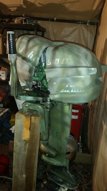
I'm bringing an old Johnson QD-16 back to life. Someone decided to paint it camo green, and then gave up on the motor. Here it is, in all it's glory, as it currently sits.


It didn't run when I got it, and it had no spark. So far, I've:
- replaced the coils and spark plugs and cleaned the points - it now has good spark
- the carburetor has been removed, cleaned and replaced
- fuel lines from the old pressure hose linkage to the carburetor and crankcase were rotten, so I'll replaced those tomorrow
- the lower unit (which is not original to the motor) was drained of oil, which was clear, but there were signs of oil leakage. I'll refill with new oil and replace the o-rings, and see what happens when I run it on the water.
- a broken prop was replaced with a prop from another 10hp outboard.
- located an old rusty pressure tank, cleaned it out inside, painted it, and when the pressure tank wouldn't pump gas, played with it until it would.

So prior to the carb clean, the motor fired up and runs, but wouldn't run at full speed, and wasn't idling well.

So - current challenges - I have three questions.
1) How do I properly set up the carburetor, including the idle and high speed screws?
2) How do I properly set up the throttle / magneto plate / cam - see the videos below, and you'll see what my difficulties are. It looks to me like someone has set it up wrong.
3) How do I properly set up the roller - for much of the time it isn't touching the cam. In addition to the cam not being set up right, my sense is the roller is also set up incorrectly (see the videos....)

Videos will follow in the next post
 
Last edited:

flyingscott

Fleet Admiral
Joined
Apr 8, 2014
Messages
7,988
First thing i would do is get the rebuild kit tank for the tank find them on ebay.
 

HighTrim

Supreme Mariner
Joined
Jun 21, 2007
Messages
10,486
Ok watched your video.

You need to be in forward gear, for the throttle to be able to advance far enough to get the roller at the edge of the brass cam.

Those two linkage points you mentioned only go on one way, they are not adjustable. You will notice on the bracket for the linkage, the holes for the shafts have one side of the hole flat, the other round, as the shaft itself has a step machined in it. So you just line up the flat part of the shaft with the flat part of the hole, then tighten down the screw.

To adjust the linc n sync, advance the throttle so that the roller is against the cam where the hash mark is machined into it. At that point, the roller should be touching the cam, and starting to open the carb butterfly, and the linkage starts to move. It should not touch at low idle, like you see on your motor. That is normal.

If the cam is not touching the roller at that point, loosen the right screw holding the cam on from underneath....the hole for that screw is elongated, so you can pivot the cam in and out to make your adjustment.

PS.....I see some Commander parts mixed in your area there!
 

pckeen

Commander
Joined
Jun 20, 2012
Messages
2,067
Ok watched your video.

You need to be in forward gear, for the throttle to be able to advance far enough to get the roller at the edge of the brass cam.

Those two linkage points you mentioned only go on one way, they are not adjustable. You will notice on the bracket for the linkage, the holes for the shafts have one side of the hole flat, the other round, as the shaft itself has a step machined in it. So you just line up the flat part of the shaft with the flat part of the hole, then tighten down the screw.

To adjust the linc n sync, advance the throttle so that the roller is against the cam where the hash mark is machined into it. At that point, the roller should be touching the cam, and starting to open the carb butterfly, and the linkage starts to move. It should not touch at low idle, like you see on your motor. That is normal.

If the cam is not touching the roller at that point, loosen the right screw holding the cam on from underneath....the hole for that screw is elongated, so you can pivot the cam in and out to make your adjustment.

PS.....I see some Commander parts mixed in your area there!


Thanks - that worked perfectly. :joyous: So that's questions 2 and 3 answered.

So my last question is: How do I set up the low and high idle knobs? Where should I set them to start, and how do I adjust them from there?
 

pckeen

Commander
Joined
Jun 20, 2012
Messages
2,067
First thing i would do is get the rebuild kit tank for the tank find them on ebay.

I've rebuilt the tank - and it's working, so I'm not going to redo this right now - but I may want to put in a new liquid liner this winter. Do you have a link to the ebay sale site? I couldn't find one.
 

Chinewalker

Fleet Admiral
Joined
Aug 19, 2001
Messages
8,902
A good starting point for the needles is 1.5 turns from closed on the top (low speed) and 1 full turn on the bottom (high speed). Adjust for best running from there. Best done on a boat, under load.

I, too, noticed the K-10! Great motors!
 

HighTrim

Supreme Mariner
Joined
Jun 21, 2007
Messages
10,486
Once you have your static settings, 1.5 out from seated for low, and 3/4 out from seated for high, take her to the lake.

First go wide open throttle. Then, turn the high speed needle, clockwise, about 1/8 of a turn at a time, until it wants to die, or stutter. Then turn it back CCW about 1/4 turn.

Then idle down low in gear. Again, in small increments, giving the motor time to respond, turn the upper, low speed needle clockwise, until it starts to lean sneeze, or want to die. At that point, back it back out 1/4 turn.

Now take off the dials, and put them back on so that they are pointing at one another. That way, you know if they have moved.]

A lot of this vintage OMC, for cold starts, like the low speed needle to be a bit rich, so to start turn the top dial a quarter to half turn CCW, then after a few seconds of running, put it back in the middle. Yours may not need to, but some like to be started rich.
 

pckeen

Commander
Joined
Jun 20, 2012
Messages
2,067
Thanks all - I'll get this set up tonight, and with any luck, I'll splash the motor and boat.
 

pckeen

Commander
Joined
Jun 20, 2012
Messages
2,067
Splash!......and back to the drawing board.

First the good news - the OMC tank has a good seal and works well - lots of pressure, no leak. The impeller is working - lots of water coming out. Goes into and out of gear without a problem. And the top cylinder? Well that runs.

Now the bad news - it idles poorly, and was hard to start. After I got it running, lots of vibration and shaking in the engine, and the engine was obviously underpowered. I ran it at full throttle, and it didn't run fast. When I unplugged the bottom cylinder, the motor's running didn't change. When I unplugged the top cylinder, it ran worse for a few seconds, then died. So I have no, or very poor, spark on the bottom cylinder.

The coils, boots, spark plugs and wires are all new. Same old condensors and points. I did adjust the points using a .020 feeler guague, but this was my first (ever) attempt at adjusting points, so I may have mucked it up. I also don't know enough to know at sight, if the points are otherwise bad.

I believe the condensers are good, because a few weeks ago, I had no spark on the lower cylinder after replacing the coils, plugs and wires. I switched the condensors, and it made no difference to whether there was spark or not. I had then cleaned the points, and got spark on both cylinders, so figured I was golden.

Guess not.

Before I start fiddling with it, what do you suggest, or what have I obviously messed up?
 

HighTrim

Supreme Mariner
Joined
Jun 21, 2007
Messages
10,486
Things to check.

Inside the spark plug boot. The spring clip to plug wire connection. Although you say you changed the wire. Are you getting good continuity through the wire through the clip?

Polish the points. Even new ones. I like to use a wire wheel on a bench grinder, but points file will work, or even wet/dry wrapped around a hacksaw blade. Then dip paper stock in acetone, and run that through to clean them properly. Then blow off with compressed air. This is after you set them at 020 with the feeler gauge, when the flywheel key is aligned with the rubbing block of the points you are setting. An 018 should go though with ease, 020 tight but allow through, an 022 should not fit through.

Did you twist the wires good into the bottom of the coil?

Your test for the condensors wont work, what if both are bad!? lol If you don't have the ability to test them, change them, they're only like 5 bucks. Especially if they have the red paper tops, toss em.
 

pckeen

Commander
Joined
Jun 20, 2012
Messages
2,067
Things to check.

Inside the spark plug boot. The spring clip to plug wire connection. Although you say you changed the wire. Are you getting good continuity through the wire through the clip?

Polish the points. Even new ones. I like to use a wire wheel on a bench grinder, but points file will work, or even wet/dry wrapped around a hacksaw blade. Then dip paper stock in acetone, and run that through to clean them properly. Then blow off with compressed air. This is after you set them at 020 with the feeler gauge, when the flywheel key is aligned with the rubbing block of the points you are setting. An 018 should go though with ease, 020 tight but allow through, an 022 should not fit through.

Did you twist the wires good into the bottom of the coil?

Your test for the condensors wont work, what if both are bad!? lol If you don't have the ability to test them, change them, they're only like 5 bucks. Especially if they have the red paper tops, toss em.


I'll start on this shortly. Another thought - I cannot get 'marine' spark plug wires out here at all, so I'm using spark plug wires from NAPA - which are presumably designed for cars. I've heard it said you shouldn't use auto wires on an outboard, but have also read a number of threads (not on here) saying it isn't a problem. Any views on this?
 

64osby

Admiral
Joined
Jul 28, 2009
Messages
6,799
It should be solid copper wires. It can be ordered online. Also think small engine repair places carry it.

I have always read not to use automotive wire, period. My .02.
 

pckeen

Commander
Joined
Jun 20, 2012
Messages
2,067
It should be solid copper wires. It can be ordered online. Also think small engine repair places carry it.

I have always read not to use automotive wire, period. My .02.

Why should it be solid copper wires? I'm sure there's a reason - just haven't been able to find one posted anywhere.
 

Crosbyman

Rear Admiral
Joined
Nov 5, 2006
Messages
4,998
I am not sure slid copper is mandatory but "metal" conductors incl twisted wire should be fine

just do not use carbon wires
 

HighTrim

Supreme Mariner
Joined
Jun 21, 2007
Messages
10,486
Do NOT use graphite auto plug wire in a magneto ignition. Never.

They have extra resistance than the metallic core wire, and you will burn out the secondary winding in your coil. They can have up to 20,000 ohms resistance, depending on the manufacturer of the wire. Also, due to the higher resistance, it limits current flow, and hence results in a weaker spark and poor combustion.

So why was it made if it is not as efficient? Well it became necessary once radios were getting installed in autos in the 60s. Metallic core wires emit RFI (radio frequency interference), or EMF (electromotive force) from the current flow in the wire getting switched on and off rapidly, creating a magnetic field. This affects the car radio, or other electronic systems. So they had to come up with a way to limit this. The graphite wire did this, by increasing resistance in the wire, hence making the whole wire a resistor.

I like copper core best, but must be metallic core. Throw that graphite wire out, to save your coils, and increase spark quality.

I didn't get into deep detail on this, but you get the idea.
 
Last edited:

pckeen

Commander
Joined
Jun 20, 2012
Messages
2,067
Ah. Thanks. Let's hope I haven't burned the coils out test running the motor. I probably have 20 minutes run time on the coils with my various starts and stops. I'll replace the wires and boots.

Interesting - this would explain why I have spark on the top cylinder (with the shorter spark plug wire), and no or poor spark on the bottom cylinder (longer wire): more wire = more resistance = less spark....
 
Last edited:

pckeen

Commander
Joined
Jun 20, 2012
Messages
2,067
I've pulled off a couple of solid core spark plug wires off another old motor - but testing with them with the multimeter gives a reading of 01 or 0.2 ohms. Are these spark plug wires bad?
 

HighTrim

Supreme Mariner
Joined
Jun 21, 2007
Messages
10,486
Spark plug wire is very cheap. Not worth doing twice, just buy it brand new. Where are you from? How far north? I buy it in the 100' roll
 
Top