Ok, for testing the coil continuity......
If you put your meter leads between the lead that goes to the points, and the ground lead, that tests your primary winding in the coil. It is a short, fat wire, and almost never fails. Even in the old coils. It should show 0 ohms resistance.
If you put your meter leads between the spark plug boot, and the ground lead on the coil, that tests your secondary winding in the coil. It is a long, thin wire, and on a bad coil is often the issue. You will get between 3000 to 8000 ohms resistance here, depending on the coil manufacturer, if it is good. The trouble with testing this one, is sometimes it is just fractured, and your meter will show continuity. Then, when the coil heats up from running, the fracture will separate from expansion, and the coil will fail. You will get back to the dock, test it, and will seem ok. That is where a tool like a Mercotronic comes in handy for testing, as it puts a load on the coil while under test.
So, if you are trying to simply test the spark plug lead, and try to put a lead on the boot, and one on the coil ground, and am expecting to see 0 ohms resistance, you wont. Doesn't mean your spark plug lead is bad.
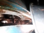
For the water line, you are correct, it is not like the newer motors. Different beast.


") The thing seems to be pretty good so I figure water pump, points/ect and it will be good to go. I might replace the head gasket just because thats easy and i can decarb it a bit.
The thing seems to be pretty good so I figure water pump, points/ect and it will be good to go. I might replace the head gasket just because thats easy and i can decarb it a bit.