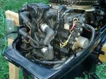
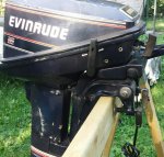
1992 15hp Evinrude, what are the wires for?

Todd in NY

Petty Officer 2nd Class
Joined
Jun 15, 2015
Messages
157
The model number is E15RLENM. It has 2 wires (red and black) that come from the front of the engine cover. I don't know if these wires are for charging a battery, powering running lights or electric start. It has a pull start, but there is a black button in place where the electric start button should be on the right side of the motor. I don't know if the motor was modified or updated by a previous owner. I use it as a kicker/trolling motor and it would be nice if this motor could keep my battery charged while I am trolling, using the battery to run my fish finder and accessories. Any thoughts?
 

Chinewalker

Fleet Admiral
Joined
Aug 19, 2001
Messages
8,902
It is possible it has an accessory charge system added. Does the red wire end at a terminal block, where it mates up with another red wire running to a small cylindrical bit? That, in turn should have a pair of yellow wires running under the flywheel. That is the rectifier that turns the AC of the charge stator into DC for the battery.
 

Todd in NY

Petty Officer 2nd Class
Joined
Jun 15, 2015
Messages
157
I'll check that when I get home from work. I know the red and black wires seem to be bundled with other wires from the tiller (if memory serves me correctly). I'll get back on here after I trace the wires. Thanks!
 

Vic.S

Rear Admiral
Joined
May 4, 2004
Messages
4,701
Almost certainly the output for battery charging.

The red and black wires together with the terminal block, rectifier and yellow wires pretty accurately describes the charging system on my Yachtwin.

Only one minor point to make is that you will find 3 yellow wires rather than the pair Chinewalker suggests

You will see the parts mentioned in the "ignition" parts diagram if you go to the BRP parts catalog.
 

Todd in NY

Petty Officer 2nd Class
Joined
Jun 15, 2015
Messages
157
Thanks Vic.S! I have some pictures to post. I found 2 black wires on the left side of the motor that were taped up. I untaped them and found one to have an eyelet and the other to have a metal end that looks like a broken eyelet. There's a black cylinder-shaped plug on the left side that will not allow the motor to start if it is plugged in together. Not even with the safety tether plugged in. But having them unplugged seems to disconnect the red kill button on the tiller handle. Also, my fuel pump shape might be that of a motor with electric start if I remember correctly (one is round and one is 5 sided). Anyway, here are some pics... 0804151945-1_resized.jpg
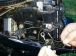

These 2 wires were taped up and tucked away. I don't know where they are supposed to go or what purpose they serve. Part # 582508 are the ignition coils, as you know.
0804151946_resized.jpg


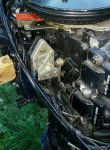
This red wire runs along the right side with a black wire. The black wire attaches to the right side of the round thing in the middle of the picture (rectifier assembly, supposed to be on electric start models?).
0804151947-1_resized.jpg


Here you can see where the black wire is attached. I don't know if these are the black and red wires from the front of the motor because they are routed underneath and out of sight once they enter through the engine cover.

0804151948a_resized.jpg


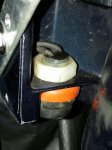
The is the black plug (possibly the kill plug) that will only allow the motor to start if the 2 halves are unplugged. Above the plug is a shiny spot that looks like something might have been attached there at one time (the 2 threaded holes).

Any help would be much appreciated, and thanks for taking the time to help me fix this mess.
 
Last edited:

Vic.S

Rear Admiral
Joined
May 4, 2004
Messages
4,701
The red wire and the black wire grounded to one of the rectifier mounting bolts are the DC output from the rectifier .

In my case these exit the lower cowl via a cable grip and were originally long enough to connect to a battery for charging . IIRC they had ring terminals in the ends but I cut them short and fitted a deck plug.

But for electric starting and/or with an electric primer obviously things will be different.

I guess the two black wires in your first picture are the wires from the steering handle (tiller) mounted stop/kill switch. One would I think have been grounded uned a coil mounting screw, The other looks as though it has been pulled from one of the cylindrical connectors. Thats how it is on my Yachtwin..


Have you looked at LeeRoy's ramblings to see if there is any useful info there. http://www.leeroysramblings.com/Outboard Motor Related/OMC outboard related articles.html

Also have a look at this service manual
http://boatinfo.no/lib/evinrude/manuals/1990-2001johnsonevinrude.html
there may be some helpful info in there. There appear to be wiring diagrams which with luck will enable you to sort things out
( It's a pain to down load and view though)
 

oldboat1

Fleet Admiral
Joined
Apr 3, 2002
Messages
9,607
[FONT=.HelveticaNeueDeskInterface-Regular]In the factory installation, there are two negative (blk) wires coming from the kill switch on the handle. One with a ring connector goes to the top stud on the top coil. The one with a pin goes into a single wire connector that has a yellow striped black wire coming on the other end from the harness (would look like the setup shown). [/FONT]

[FONT=.HelveticaNeueDeskInterface-Regular]It may be that a PO was trying to hook up a manual stop switch (button you describe on the cowling). If so, the black wire currently going into the connector shown may be one of the wires from that button. I would try to hook up the original kill switch first, disconnecting wiring from the button on the cowling, whatever it is —-- think the original kill switch wires are probably the two you are showing in the pic.[/FONT]

[FONT=.HelveticaNeueDeskInterface-Regular]Beyond that, the rectifier has no apparent connection to the stator under the flywheel, as would be needed for a charging system. Guessing the red wire coming into the rectifier from the front might be the start of a wire harness/battery connection set up by the PO. An electric start would also have a red lead from the rectifier to a neutral safety switch installed down in the pan, ahead of the rectifier. The switch would be wired (+) directly through the n.s. switch to a starter on the other side of the head, behind the fuel pump. That drilled area might be an attempt to install a starter bracket. [/FONT]
 
Last edited:

Vic.S

Rear Admiral
Joined
May 4, 2004
Messages
4,701
In the factory installation, there are two negative (blk) wires coming from the kill switch on the handle. One with a ring connector goes to the top stud on the top coil. The one with a pin goes into a single wire connector that has a yellow striped black wire coming on the other end from the harness (would look like the setup shown).

It may be that a PO was trying to hook up a manual stop switch (button you describe on the cowling). If so, the black wire currently going into the connector shown may be one of the wires from that button. I would try to hook up the original kill switch first, disconnecting wiring from the button on the cowling, whatever it is ?-- think the original kill switch wires are probably the two you are showing in the pic.

Beyond that, the rectifier has no apparent connection to the stator under the flywheel, as would be needed for a charging system. Guessing the red wire coming into the rectifier from the front might be the start of a wire harness/battery connection set up by the PO. An electric start would also have a red lead from the rectifier to a neutral safety switch installed down in the pan, ahead of the rectifier. The switch would be wired (+) directly through the n.s. switch to a starter on the other side of the head, behind the fuel pump. That drilled area might be an attempt to install a starter bracket.


Fixed that for you so that we can read it without an electron microscope

You can see the three yellow wires coming from the stator in the second picture, although its difficult because all the wires have black sleeves on them . Thye go to the same three terminals on the terminal block as the three yellows from the rectifier


http://forums.iboats.com/filedata/fe...6012&type=full
 
Last edited:

Todd in NY

Petty Officer 2nd Class
Joined
Jun 15, 2015
Messages
157
Thanks for the all the assistance! I can't stand to have wires disconnected and taped up, and electrical systems not functioning the way they are intended to. I'll get this thing wired correctly in due time. I've been on LeeRoy's Ramblings web site, but I was looking for some other information the last time I visited there. I'll look again and see what I can find in regards to the wiring.
 

oldboat1

Fleet Admiral
Joined
Apr 3, 2002
Messages
9,607
circling back (waiting for paint to dry on a porch project). On the rectifier hook up, would expect to see yellow wires (w/stripes) coming from the stator, but don't see them -- looking for hook ups mating with the yellow wires from the rectifier shown in the pic. So think that hook up is at least (or maybe at best) incomplete.

On the stop switch though -- see one hook up that looks correct (coming into the single pin connector), but can't tell if it's coming from the trip switch on the handle or a button that a PO was installing. Whatever switch is used, there will be one wire to the mounting bolt on the coil, and another to the connector as shown in the pic. I suppose you could hook up two stop switches that way, and either one would short out the motor if activated.

Think the stop switch issue is the important one if trying to get the motor up and running. Then maybe explore what the other innovations were. (If that rectifier is in fact wired to the stator with the single red wire, think there is a possibility the connection could short out the engine, or interrupt a proper ignition loop. Not sure.)
 

Todd in NY

Petty Officer 2nd Class
Joined
Jun 15, 2015
Messages
157
I'll have to take a closer look at those wires after work today. The 2 black wires look like they come from the tiller handle and red kill button on the tiller handle. The black wire with the yellow stripe on it (the one on the black plug) is connected to the bolt under the bottom ignition coil if I remember correctly.

0804151947a-1_resized.jpg

0804151949-1_resized.jpg

Those are the 2 black wires running alongside the fuel pump.
 

Todd in NY

Petty Officer 2nd Class
Joined
Jun 15, 2015
Messages
157
I might add that the engine starts easily (with the rope starter) and runs great in neutral, forward and reverse. I just have to leave the black plugs unplugged or it won't start. And again, once it is running with the plug unplugged, I have to kill the motor by turning the throttle all the way down and holding it there until the motor dies from low idle.

If I have the engine running, how can I test the 2 wires coming out the front of the cowling to see if they are producing any current? I have a multi meter but I'm no genius when it comes to electricity troubleshooting. (you might have already guessed that by now :confused:)
 

Vic.S

Rear Admiral
Joined
May 4, 2004
Messages
4,701
I might add that the engine starts easily (with the rope starter) and runs great in neutral, forward and reverse. I just have to leave the black plugs unplugged or it won't start. And again, once it is running with the plug unplugged, I have to kill the motor by turning the throttle all the way down and holding it there until the motor dies from low idle.

If I have the engine running, how can I test the 2 wires coming out the front of the cowling to see if they are producing any current? I have a multi meter but I'm no genius when it comes to electricity troubleshooting. (you might have already guessed that by now :confused:)


Set your meter to a DC volts range ( 20 volts for example) and connect it to the two wires You should get a reading perhaps around 12 volts at idle but rising up to 14 and above as you increase the rpm.

Then you really need to check that you can get a decent number of amps. The easiest would be to connect to a 12 volt bulb. I'd guess that that engine has a 5 amp stator ( perhaps a bit more but not a lot more with that type of rectifier). It should light a 50 watt car headlamp bulb.

The way you are stopping the engine is quite unsatisfactory. I would urge you to sort that out and reconnect the tiller mounted stop button ( or a remote stop button) so that you can use the emergency kill lanyard. . A boat with a 15hp engine might not kill you if you fall overboard and it runs over you a few times but the prop could sure inflict some nasty life changing injuries!
 

Todd in NY

Petty Officer 2nd Class
Joined
Jun 15, 2015
Messages
157
Thanks, and I agree 100% about fixing the kill switch before I use the motor. That's why the motor is sitting on a saw horse and I'm using this forum to try to sort out what all these loose wires are for. I think the PO tried to modify this motor and make it do something it wasn't intended to do, or he did some shortcut jerry rigging and never got it working right, and never returned it to OEM specs.
 

oldboat1

Fleet Admiral
Joined
Apr 3, 2002
Messages
9,607
can see the yellow wires from the stator now, and do seem to be routed right with the rectifier wiring. curious to see how the battery is wired, but charging system might have a chance (if the rectifier good). VicS. had it right. Stop switch should be easy to hook up, or troubleshoot and hook up. All good.
 

Todd in NY

Petty Officer 2nd Class
Joined
Jun 15, 2015
Messages
157
I was going to look into it more tonight after work but some moron took out my mailbox while I was at work, so I spent the evening putting a new post under my mailbox. My mailbox is 30 feet before a stop sign, so I'm not sure why it gets hit every 2 years. I think it was the local DOT guys cutting grass with a tractor. They were nice enough to stick it back in the ground like nothing ever happened. When my son opened the mailbox to get the mail, it fell over because the 4x4 was broke completely in 2.

I do appreciate everyone's assistance. I'll plug away at it and post when I get it working right, and what it took to get it right.
 

Todd in NY

Petty Officer 2nd Class
Joined
Jun 15, 2015
Messages
157
Slight update on the wiring...

I traced those 2 wires in my hand (photo on page 1) and they seem to go to a black button on the right side of the motor. The black button seems to be where the electric start button should be but there is NO electric starter on this motor. That female socket connector fits over the black male pin connector inside the rubber killed plug. It looks like this motor has that black button on the right side of the motor hooked up as an alternate kill button. The red and black leads on the front of the motor are the same wires that lead back to the right side of the motor, but I haven't had time to see if they are putting out DC power yet. I disconnected the black wires on the red kill button on the tiller handle and replaced them with the 2 other black wires, and I will hopefully get a chance tomorrow to start the motor and see if that black button is in fact another kill button. Has anyone ever seen a kill button where this black button is? This button and the wiring looks like it was professionally done. It's the black button in front of the F-N-R lever.
0726151714c-1_resized.jpg
 
Last edited:

oldboat1

Fleet Admiral
Joined
Apr 3, 2002
Messages
9,607
looks to me like there is still a starter button in there -- under the manual starter handle. You should be able to reach under the bracket there and feel the starter button assembly if it's there. The '80s models had a stop button on the side where you apparently have a button -- not sure what the intent was, but if a stop button it would have required two negative leads. Simple set up -- can make it work as a stop button with two wires from the button (tape the red one black so you will remember it's negative).

But if there is a partially wired start button in there, can't say what you have. Hard to make it work without a starter:joyous:

[factory setup with the starter button under the bracket, where it appears you have a button. Kill switch would be the red button on the transom handle assembly. Opening over on the other side -- that other button? -- for remote throttle cable.]
 
Last edited:

Todd in NY

Petty Officer 2nd Class
Joined
Jun 15, 2015
Messages
157
Mine doesn't look like it ever had an electric starter. It would be mounted behind the fuel pump, I think... Also, my serial number says it's a rope start E15RLENM. Maybe someone was in the process of converting it over to electric start and never finished. It was owned by a grandson of someone who owned a marina, so no telling if one of the marina techs modified it with one of those 80's kill buttons.

I just took a picture of the back side of that button, looks like some bare copper wire showing on one of the wires, and both wires are black like the ones I'm holding in a previous pic. Interesting to say the least.
0808152226a-1_resized.jpg
 
Last edited:
Top