85 force prop cone???

Frank79

Seaman Apprentice
Joined
Dec 27, 2014
Messages
41
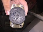
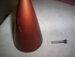
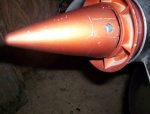
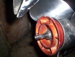
I have a 85 force outboard engine at one time had the standard prop cone at the end of the propeller. I thought there was a counter pin holding it in place over the years. Thru time and props, the cone has since been long gone. I was able to find a new old stock from quick silver. It came with the standard screw as well. Everything matches up correctly except the big problem is there is no where for the screw to thread into. It has had a couple Michigan props on it for several years now. Is there something I'm missing such as a different prop nut?
 

Frank Acampora

Supreme Mariner
Joined
Jan 19, 2007
Messages
12,004
There were two different "standard" cones. There was one white plastic version, threaded 1/2 inch and held in place with a cotter pin. This cone was used on the earlyier Chrysler two piece lower unit. It secured a thrust pin that went through the prop hub and the prop shaft.

The second cone, which is the one you need, is black plastic, is longer, and more finely tapered. It is not threaded but slips over a 1/2 inch diameter extension of the prop shaft. It sits in front of the flare washer. Thee is a 3/16 diam hole in the prop shaft extension. The cone is held in place by the same pin used to pivot the shift yoke. This is a plain pin with a slotted head and only about the top 1/4 inch threaded. the cone has a hole drilled clear through at the base and there is a flat cast into one side. This side has threads. They often strip and you then have the option of Heli Coil stainless 1/4 X 20.

Later Force engines did not have the prop shaft extension and the cone can not be used with these lower units.
 
Last edited:

Frank Acampora

Supreme Mariner
Joined
Jan 19, 2007
Messages
12,004
If you look on ebay, there are usually several of the correct cones for sale listed under Chrysler Force Propellers. Sometimes you also come across a flare washer.

But there are none for sale today, only the spacer/flare washer and a smaller tail cone for a 60 HP engine. However, you can run your engine without the flare washer and tailcone. There is no difference in performance. It only looks better.
 
Last edited:

Frank79

Seaman Apprentice
Joined
Dec 27, 2014
Messages
41
Frank, the parts came in and we will be installing them tonight to see if this solves the rocking. Where could I find the extension you mentioned for the prop cone?
 

Frank Acampora

Supreme Mariner
Joined
Jan 19, 2007
Messages
12,004
Sorry if I was unclear. The extension is a 1/2 inch diameter part of the prop shaft. It is not a separate piece. Very early Force engines had this prop shaft but later models did not. If the prop shaft does not have this "extension" you can not use the tail cone. You can use the flare washer and indeed you will need some sort of a thick spacer because the splines do stick out of the prop hub by about 3/16 inch. If you do not have the flare washer several large stainless washers will do. Chrysler or Force did make a bronze spacer of the correct size and thickness.
 

Frank79

Seaman Apprentice
Joined
Dec 27, 2014
Messages
41
Frank, thanks for the info. I'm still trying to remove the top motor mounts and they don't move from their place. Am I missing a bolt or something? The side motor mounts and screwed in and were easy to replace
 

Frank Acampora

Supreme Mariner
Joined
Jan 19, 2007
Messages
12,004
Top motor mounts are each held by two bolts: Both are 3/8 diameter. The bottom bolts are visible from the outside underneath the plate that holds the kingpin and lower motor mount--I forget what it is called. UNFORTUNATELY the top bolts are connected to the midleg and are under the match plate. The engine block needs to be removed to access them.

On the positive side--I have never seen a broken upper motor mount. It just doesn't seem to happen. Probably because there is a stop on the back of the lower cowl that limits the movement of the midleg. This is a bent piece of 1/4 inch stainless held to the cowl by four 5/16 screws. There is usually about a 1/4 inch gap between the protrusion on the midleg and the stop. Do not try to remove the stop. The bolts do tend to corrode and there is a good chance that one or two will snap,

SO: Unless you can actually see damage to the upper mounts, replace the lower bolts and leave them alone. That is, unless you enjoy removing an engine block..
 

Frank79

Seaman Apprentice
Joined
Dec 27, 2014
Messages
41
Well Frank, you are so correct! Sadly, we didn't get to read your last post before we removed that lower shock. And guess what? Snap goes a bolt! Just as you stated those 4 bolts are very corroded from 30 years of boating. We were able to remove 3 out of the 4. I will leave the top motor mounts alone as I don't see and reason now to mess with them. I will however replace that lower mount. The sides have been replaced already and I have found that the rubber seal that goes around the engine was very dry rotted. I have a new one so that will be put on. Does that black seal do anything to prevent rocking of the engine or does it just work as a seal so water doesn't go up?
 

Frank79

Seaman Apprentice
Joined
Dec 27, 2014
Messages
41
Lower shock
 

Attachments

  • FADBA0EB-6462-4A71-A6E9-24F2A6B86D90.jpg
    FADBA0EB-6462-4A71-A6E9-24F2A6B86D90.jpg
    176.4 KB · Views: 0

Frank Acampora

Supreme Mariner
Joined
Jan 19, 2007
Messages
12,004
The rubber ring seal is actually a noise attenuator. When new, it will help keep water out of the outer shroud but really, it doesn't matter if water gets in--it will drain out when running at plane. It is so soft that if you have a broken motor mount the midleg will rock and compress it.

On the plus side, the bolt snapped in the motor mount, not the midleg. Thus, you can replace it with a stainless 5/16 bolt from the big box store. When you go to remove the other part of the motor mount, sprat all four bolts with penetrant and let sit for a couple of days, spraying every day. Remove the two bolts on one side and loosed the two bolts on the other side Then slide out the motor mount mounting plate.
 

Frank79

Seaman Apprentice
Joined
Dec 27, 2014
Messages
41
Were you able to see the picture I posted? I want to make sure I did it correctly
 

Frank Acampora

Supreme Mariner
Joined
Jan 19, 2007
Messages
12,004
Ah, well! It is no fun but it can be done. Buy a cobalt steel drill bit set (not the brand Kobalt which is not worth stealing). Dewalt makes a good one at about 30 bucks.. Start with a small bit and drill out the broken bolt progressing to the correct size. Use slow speed and lots of pressure. High speed will simply melt the drill bit. Get to the proper size for re-tapping 5/16 X 18 ant re-tap the hole. If you really mess up use a stainless heli-coil
 

Frank79

Seaman Apprentice
Joined
Dec 27, 2014
Messages
41
Frank, do you have the diagram for the prop assembly for my engine? I do have the force book as well. It seems that the prop is grinding on metal if the spacer is placed where it should be. The prop still spins freely but you can hear it,( we only hand spun it.) if we take the spacer out the grinding goes away. I'm thinking there's another part that's missing behind the prop that somebody lost
 

Frank Acampora

Supreme Mariner
Joined
Jan 19, 2007
Messages
12,004
I don't have a diagram but there should be a thrust washer behind the prop and a 1/4 inch thick spacer under the prop nut and washer.Look up any Force lower unit diagram on one of the parts suppliers.
 

Frank Acampora

Supreme Mariner
Joined
Jan 19, 2007
Messages
12,004
No Title

Well, I am finally able to post photos. Unless your prop shaft looks like this, you can not use the tailcone. This particular one is using the flare washer because I think it looks good. The photo of the prop show the thrust washer on the left and the spacer (you can substitute the flare washer) on the right. Notice that although it is a single exhaust lower unit, I am using a stainless thru-hub exhaust prop and notice that the flare washer barely fits inside.--but it does. Also notice the shift pivot screw that locates the tailcone on the propshaft.
 

Attachments

  • photo227457.JPG
    photo227457.JPG
    331.5 KB · Views: 0
  • photo227458.JPG
    photo227458.JPG
    383 KB · Views: 0
  • photo227459.jpg
    photo227459.jpg
    225.1 KB · Views: 0
  • photo227460.jpg
    photo227460.jpg
    183.6 KB · Views: 0
Last edited:
Top